Volumetric
Lighting (or Crepuscular Rays or Light Shafts or God Rays) describes the
phenomenon of light-interaction with the participating media. Light doesn’t travel
through the void, but gets absorbed and reflected by many small particles,
which is also called the Tyndall
effect. Much like the bloom effect, it raises the perceived contrast of a scene.
There are
many techniques to simulate volumetric lighting. Some games additively render
transparent polygons (e.g. around the silhouette of a window). On faster
graphics hardware, you can also perform a ray casting on the shadow map. In
this tutorial, the approach from Kenny Mitchell from GPU Gems III is used.
The advantage is that it can be implemented very easily as a post-process
shader without rendering from the light’s view. A rather major restriction is
that the light source has to be visible for this effect to work. If you imagine
a scene where you look along a wall at a grazing angle with light falling
through the windows, this technique wouldn’t be able to produce
volumetric lighting.
Unfortunately,
volumetric lighting is one of the most over-used effects in games. Often it is
used regardless whether it might be realistic that there are particles of dust or water in the air, or not. As all
other lighting and post-screen effects, it is best subtle and only in scenes, where it is realistic.
I have been
thinking long and hard how to organize this presentation of the source code. I
decided to describe only essential parts of the program to keep the tutorial
brief. I assume that you are familiar with graphics programming in general and
with the XNA framework. I am not going to describe how to load and rotate a
model or how to initialize the view and projection matrices. If you want to
start from there, I strongly suggest to read Riemers
XNA Tutorial, a great site with many good code examples.
Scene Setup and Modeling
As
mentioned before, volumetric lighting might be a very intensive effect if and
only if it is used right. Otherwise, it will just look cheap and harm the
overall impression of your game. In order to make it look real good I decided to put some
effort in the creation of the scene. I chose a setup consisting of several
rotating cogs: As they are constantly rotating and overlapping, they create a lot of little gaps and wholes where
the light can shine though. This is a very good condition for volumetric
lighting, since the light beams will continuously split and merge as seen in
the tutorial video.
I had
little success searching the web for free 3d models of cogs, so I spent some
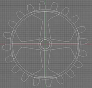
hours on how to create them manually with Cinema 4D. As you can see in figure
1, I first combined several splines using simple boolean operations. The
result is a two-dimensional set of curves that look very much like a cog we
could use, except for they are 2D. Then I found out that you can extrude and
polygonize the splines, resulting in a perfect 3D cog as shown on the right
side of figure 1.1. The next problem with Cinema 4D is that the build-in
DirectX file export sucks hard. Fortunately, some guys wrote a very good
plug-in called XPort to convert
.c4d into .x files.
(Figure 1: Modeling the cogs with Cinema 4D)
I am a
programmer and not an artist, but it turned out to be real fun to create my own
3D models. Something I yet couldn’t deal with was to parameterize the cogs for
texture mapping, which would have been really useful to create a more realistic
material. By the way, all the x-files can be found in the project source code!
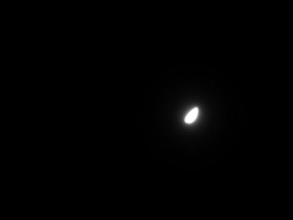
Creating the Light Source
This is
definitely the easiest part: The light source is a simple bitmap that is loaded
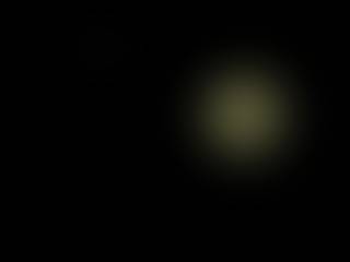
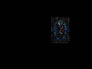
into a Texture2D object. In figure 2 you can see two examples: The image on the
left side is created with Photoshop by drawing a circle with gradient fill from
yellow to black. After applying a strong Gaussian blur I reduced contrast and
brightness by -40 units (I did that because Mitchell seems to use very dark
bitmaps as well). On the right side I took a photograph from a church window,
resulting in differently colored light rays.
(Figure 2: Top: Examples for unstructured and structured light sources. Bottom:
Final Results.)
Scene Rendering
The program
begins with the already defined Initialize( ) method. Note that code in bold doesn’t belong the XNA
framework. Such code is part of the program logic or my post processing library
which comes along with the project files.
As you can
see, I start by creating the matrices and rendertargets . Then I create an
instance of the class PostScreenFilters. This
is the post processing library, which I separated from the program logic
because there are routines I use over and over again. The library can be
understood as some kind of toolbox to perform real-time blurs, MipPap-level
creation, volumetric lighting, ambient occlusion and so on.
protected override void Initialize( )
{
SetupMatrices( );
SetupRenderTargets( );
// the library just needs to know
the resolution and the graphics
// device
_PostScreenFilters = new PostScreenFilters(
_Width,
_Height,
GraphicsDevice,
Content );
InitializeGears( );
base.Initialize( );
}
Here is the
code for the viewing parameters. The camera is placed on the positive z-axis as
we are looking along the negative z-axis. I keep the range from the near to far
plane rather small in order to have maximum precision of the z-buffer. Not much
talking here.
private void SetupMatrices( )
{
float AspectRatio = ( float )
_Width
/ ( float ) _Height;
Vector3 CameraPosition = new
Vector3( 0f, 0f, 30f );
For the volumetric lighting effect I need seven render targets.
Two are required for the models drawn once colored and once black (for the mask
image). The others ones are more or less just intermediate targets used by post
screen effects, for example extracting luminance values above a certain
threshold, scaling the image to half resolution and re-scaling it to full
resolution again. There is of course also a target which holds the final
result.
private void SetupRenderTargets( )
{
// just the gears with lighting and
material
_RenderTargetColor = new RenderTarget2D(
GraphicsDevice,
_Width,
_Height,
1,
SurfaceFormat.HalfVector4 );
// post-processing: only luminance
values above certain
// threshold
_RenderTargetLuminance = new
RenderTarget2D(
GraphicsDevice,
_Width,
_Height,
1,
SurfaceFormat.HalfVector4 );
// temporal render target for
additive blending
_RenderTargetTemp = new
RenderTarget2D(
GraphicsDevice,
_Width,
_Height,
1,
SurfaceFormat.Vector4 );
// the gears drawn black
_RenderTargetMask = new
RenderTarget2D(
GraphicsDevice,
_Width,
_Height,
1,
SurfaceFormat.HalfVector4 );
// post-processing: the screen in
half resolution
_RenderTargetShaftsHalf = new
RenderTarget2D(
GraphicsDevice,
_Width / 2,
_Height / 2,
1,
SurfaceFormat.HalfVector4 );
// post-processing: the screen
scaled to full
// resolution
_RenderTargetShaftsFull = new
RenderTarget2D(
GraphicsDevice,
_Width,
_Height,
1,
SurfaceFormat.HalfVector4 );
// all render targets combined
_RenderTargetFinal = new
RenderTarget2D(
GraphicsDevice,
_Width,
_Height,
1,
SurfaceFormat.HalfVector4 );
}
The method RenderScene( ) creates the world matrix,
the inverse transposed world matrix for the rotation of the normal vectors and
the inverse view matrix for the viewing direction. These are matrices which are
later passed to the vertex shader in the effect file. First, the parameter effect is assigned to every meshpart of
the model. It determines whether the model is draw normally (i.e. with its
material properties) or plain black (for the mask render target).
private void RenderScene(
RenderTarget2D Destination,
Effect Effect,
Matrix View,
Matrix Projection )
{
// world, world inverse transpose
and view inverse
Matrix World, WorldIT, ViewI;
// apply effect parameter to model
Model CurModel = _GearModel1;
foreach( ModelMesh mesh in
CurModel.Meshes )
{
foreach ( ModelMeshPart part in
mesh.MeshParts )
{
part.Effect = Effect;
}
}
Before rendering the models, all required
render states are saved. Note that this is regarded as good and save
programming style!
The code so
far was not too difficult to understand. Now for the more complicated stuff. As
expected, I start by drawing the same scene with two different materials
(effects) into two different render targets using the previously explained
method RenderScene( ).
protected override void Draw( GameTime
gameTime )
{
// render the scene in black
RenderScene(
_RenderTargetMask,
_EffectBlack,
_WorldView,
_WorldProjection );
// render the scene with material
and lighting
RenderScene(
_RenderTargetColor,
_GearMaterial,
_WorldView,
_WorldProjection );
Now there is one render target holding a colored version of the cogs and
another with plain black cogs. Note that in the mask image, all pixels that
were not processed by the fragment shader, have an alpha value of zero. This is
because in the next step, the additive blending, we want those pixels to have
no contribution! The code below performs this task.
In figure 3 you see the result of the blending operation.
(Figure 3: Result of the additive blending of
background and black gears.)
Next comes this peculiar line of code:
// create mipmap levels of the
resulting target
RenderTarget2D[
] MipLevels =
_PostScreenFilters.CreateMipMapLevels(
_RenderTargetTemp );
That method is part of my post processing library. What it does is
actually simple: It takes a render target and creates six downscaled versions
of it. In this case, the variable MipLevels[ 0 ] holds the image with half
resolution, MipLevels[ 1 ] a fourth of the resolution and so on (future driver
generations should do that automatically). In figure 4 such a mip map chain is
shown:
(Figure 4: The hand-generated MipMap chain of
the masked render target.)
Now comes the very heart of the effect, the method LightShafts( ). It receives a source render target, in this case
our masked image in half resolution, a destination render target to write to and
several shader parameters, for example the light source coordinates in 2D and
several scalar values to describe attenuation and falloff. I refer to the
original article by Mitchell for the meaning of these parameters. I will
explain the source code of this method later in the tutorial!
// perform the light shafts on half
of the resolution
_PostScreenFilters.LightShafts(
MipLevels[ 0 ],
_RenderTargetShaftsHalf,
_LightMapPosition,
1.0f,
_LightShaftDecay,
1.0f,
_LightShaftExposure );
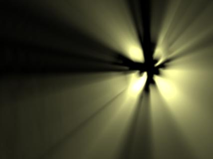
The result in the destination target looks like shown in figure 5.
Mitchell applies the effect to a sixteenth of the original resolution, but I
found that the result looks better at half resolution, because that yields
higher frequencies which look more “streaky”.
(Figure 5: The volumetric lighting shader
applied to the half resolution masked image.)
Next step is to re-scale the image in figure 5 back to full screen
resolution. This is done with a command from my library as well:
// up-scale the effect
_PostScreenFilters.HalfToFullscreen(
_RenderTargetShaftsHalf,
_RenderTargetShaftsFull );
The next thing differs from what Mitchell does. In order to make the
perceived contrast even higher, I apply a bloom effect on the image we have
created so far. The bloom effects consists of three steps:
1. Extract high luminance values (“bright” pixels)
2. Blur those values only
3. Additively render them over the original image
The extraction of the very bright pixels requires a source, a destination,
a threshold and a scale factor. This is only possible because we use floating
point render targets. Otherwise, all color values would have been clamped to
the interval [0, 1]. The scaling factor is a trick: Lets say you extract a
luminance value of 1.2. If you apply a gaussian blur on that, the result is
very dark. Instead we can scale all extracted values by the factor 5.0, for
example. After the scaling, the gaussian blur is more intensive.
// extract luminance values above
threshold
_PostScreenFilters.ExtractHighLuminance(
_RenderTargetShaftsFull,
_RenderTargetLuminance,
_LuminanceThreshold,
_LuminanceScaleFactor );
The next method AdditiveBlend( ) is more
complicated: It first downscales the image to smaller levels of resolution,
exactly the same way the method CreateMipMapLevels( )does. To every level a 3 tap gaussian
kernel is applied. Note that this is a very small kernel size. Then, I re-scale
the levels up to full resolution step-by-step using a linear filter (average of
left, right, upper and lower neighbours). The result is a very smooth blur as
shown in the right image in figure 6.
(Figure 6: Left: Only luminance values greater than
1 extracted from the effect. Right: Result after full screen Gaussian filter.)
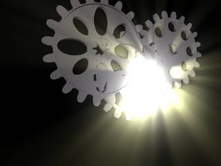
Now we’re almost done! The last thing is to additively blend all the
intermediate results. For this purpose, the volumetric lighting effect at full
resolution, the blurred luminance and the colored version of the gears are
blended together on the final render target as shown in figure 7.
Let’s conclude: These are the three render targets that we’ve additively
blended. From left to right: The volumetric lighting effect, the high luminance
values with gaussian blur and the colored gears:
+
+
(Figure 7: Blending the intermediate results.)
Finally, the result is drawn on the screen.
// draw them on the screen
spriteBatch.Begin(
SpriteBlendMode.None,
SpriteSortMode.Immediate,
SaveStateMode.SaveState );
spriteBatch.Draw(
_RenderTargetFinal.GetTexture(
),
Vector2.Zero,
Color.White );
spriteBatch.End( );
base.Draw( gameTime );
}
This is absolutely what we wanted!
The Post Processing Library
I have to
skip this part because currently it is summer term at my university and my free
time is rare. As I mentioned before, all the source code of the post processing
library is included to the project files, so you can look it up yourself. But
be warned, some of the code is pretty ugly. I guess that about 60% of the code
necessary for the volumetric lighting effect is the post processing library.
Feel free to send me an email if anything is unclear.
The Light Shafts Shader
At least
one method of the post processing library will be discussed now! It receives
the source image, the destination image, the position of the light source and
the shader parameters as defined by Mitchell. Together with the source image,
these parameters are passed to the effect file. The parameters ViewportSize,TextureSize and
MatrixTransform are required for the SpriteBatchVertexShader.fx
file which belongs to the XNA framework. You have to include this file into
your post processing shader if you want to use higher shader models than 1.0 or
1.1.
This is the
shader code which is pretty much copied from Mitchell. Note that you have to
use SM 3.0 to be able to use loops! Even better would be SM 4.0 since it allows
loops of variable length, while in SM 3.0 we have to stick to a define.
At the
beginning of the game-file you find a region that allows you to control the
most important variables of the effect. For example, if you change the
background image, you also have to change the variableLightMapPositionto define the 2D coordinates (I
simply chose the center) of the light source.
#region Application Controls
private Vector2_LightMapPosition= new Vector2( 0.7f, 0.44f );