Script Computer Engeneering - Part IV
4. Combinatorial Circuits and their Optimization |
||||||||||||||||||||||||||||||||||||||||||||||||||||||||||||||||||||||||||||||||||||||||||||||||||||||||||||||||||||||||||||||||||||||||||||
|
||||||||||||||||||||||||||||||||||||||||||||||||||||||||||||||||||||||||||||||||||||||||||||||||||||||||||||||||||||||||||||||||||||||||||||
| 4.0 Synthesis of Circuits | ||||||||||||||||||||||||||||||||||||||||||||||||||||||||||||||||||||||||||||||||||||||||||||||||||||||||||||||||||||||||||||||||||||||||||||
|
There are endless many Boolean terms and Boolean expressions and therewith many circuits they realize. Boolean functions can be represented as Normal Form by Boolean expressions,which are the cause of too complex circuits. To minimize complex circuits you should define the simplest and most inexpensive Boolean term concerning cost measures. <back> |
||||||||||||||||||||||||||||||||||||||||||||||||||||||||||||||||||||||||||||||||||||||||||||||||||||||||||||||||||||||||||||||||||||||||||||
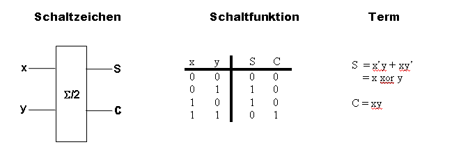
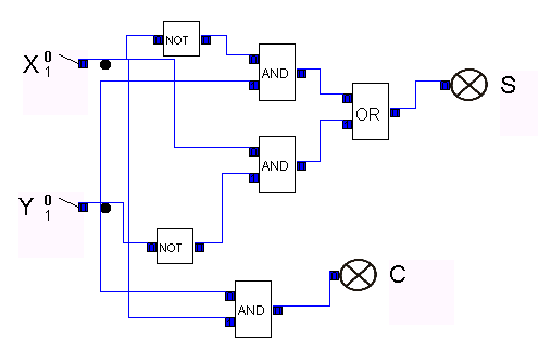
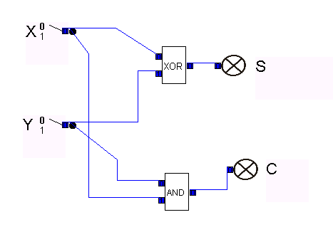
| 4.1 Half Adder | ||||||||||||||||||||||||||||||||||||||||||||||||||||||||||||||||||||||||||||||||||||||||||||||||||||||||||||||||||||||||||||||||||||||||||||
|
The realization of half adder can be gained from the Boolean terms.
|
||||||||||||||||||||||||||||||||||||||||||||||||||||||||||||||||||||||||||||||||||||||||||||||||||||||||||||||||||||||||||||||||||||||||||||
| 4.2 Full Adder | ||||||||||||||||||||||||||||||||||||||||||||||||||||||||||||||||||||||||||||||||||||||||||||||||||||||||||||||||||||||||||||||||||||||||||||
|
A full adder handles larger binary numbers in combination with a half-adder, and can carry over numbers.
For larger numbers, more full adders are used - one for each digit in the binary numbers added.
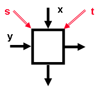
A circuit must be developed that can add three one-digit binary numbers. Instead of examining all eight possible cases and of compilating proper circuits for the outcome, it is easier 1. to add the first both binary numbers with half adder and then 2. to add the third binary number to the outcome It is important that by each or at most by one of additions carry can occur. The full adder is to add three one-digit binary numbers. It has three inputs x, y und Ci ("carry in") and two outputs S ("sum") and Co ("carry out"). The three binary numbers lie in the three inputs. The last sum position (0 or 1) lies in the output S, carry (1 or 0) lies in the output C. 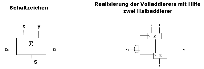
<back> |
||||||||||||||||||||||||||||||||||||||||||||||||||||||||||||||||||||||||||||||||||||||||||||||||||||||||||||||||||||||||||||||||||||||||||||
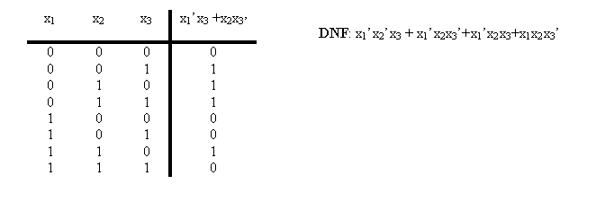
| 4.3 Minimum Polynomials | ||||||||||||||||||||||||||||||||||||||||||||||||||||||||||||||||||||||||||||||||||||||||||||||||||||||||||||||||||||||||||||||||||||||||||||
|
Polynomial is a disjunction of monomials. A low-cost polynomial to realize f is called minimal polynomial of f. An example for polynomial:
|
||||||||||||||||||||||||||||||||||||||||||||||||||||||||||||||||||||||||||||||||||||||||||||||||||||||||||||||||||||||||||||||||||||||||||||
| 4.4 Resolution Rules: | ||||||||||||||||||||||||||||||||||||||||||||||||||||||||||||||||||||||||||||||||||||||||||||||||||||||||||||||||||||||||||||||||||||||||||||
|
Simplification of the DNF above: x1’x2’x3 + x1’x2x3’+x1’x2x3+x1x2x3’ = x1’(x2’ + x2)x3 + (x1’ + x1)x2x3’ according to complement rule is x2’+x2 = 1 = x1’1x3 + 1x2x3’ and 1*x = x = x1’x3 + x2x3’ This way of siplification is known as "resolution rule", i.e. if there are two monomials in a polynomial, which differ from each other in exactly one complementary variable, then these two monomials can be substituted by their common literal. An example of multiple application of resolution rule): Examine: f(x1,x2,x3,x4) = x1x2’x3x4 + x1x2’x3’x4 + x1x2x3x4 + x1’x2’x3’x4 + x1’x2’x3x4 = x1x2’x4 + x1x3x4 + x2’x3’x4 + x1’x2’x4 = x2x4 + x1x3x4 + x2’x3’x4 The multiple application is based on the law x + x = x, which allows to double monomials: x1x2’x3x4 + x1x2’x3’x4 = x2’(x1x3x4 + x1x3’x4) = x2’(x1x4(x3 + x3’)) = x2’(x1x4)1 = x2’x1x4 = x1x2’x4 <back> |
||||||||||||||||||||||||||||||||||||||||||||||||||||||||||||||||||||||||||||||||||||||||||||||||||||||||||||||||||||||||||||||||||||||||||||
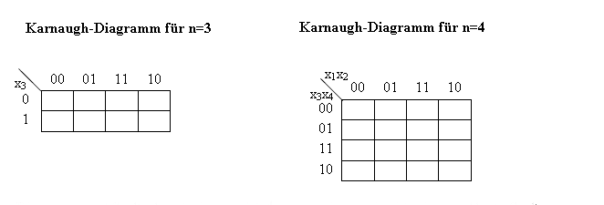
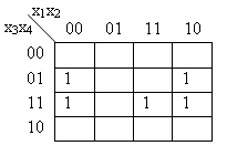
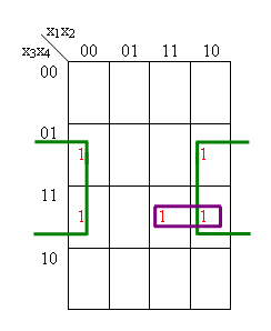
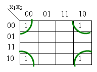
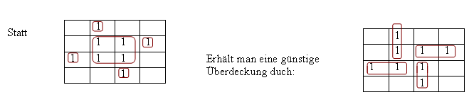
| 4.5 Karnaugh Method: | ||||||||||||||||||||||||||||||||||||||||||||||||||||||||||||||||||||||||||||||||||||||||||||||||||||||||||||||||||||||||||||||||||||||||||||
|
A Karnaugh-Map of a switch function with four or three arguments (f:2 n --> 2, n=3 or n=4)
is a graphical realization of f by: a Boolean 2x4-Matrix* for n = 3 and by a Boolean 4x4-Matrix for n = 4. * m x n-Matrix is a line-up of mn numbers in a triangle array of m-rows and n-columns.
The marking of rows and columns is to be done so, that two cyclic adjacent columns or rows differ in exact one component (or variable, or literal).
It is to take into account that two adjacent 1's in the Map provide a resolution and each field with 1 corresponds to a minterm of DNF.
double-block: x1x3x4
Note: 2. In rare cases it is reasonable not to build the largest blocks. The simplification of block number is relevant, too. |
||||||||||||||||||||||||||||||||||||||||||||||||||||||||||||||||||||||||||||||||||||||||||||||||||||||||||||||||||||||||||||||||||||||||||||
| 4.6 Implicant und Prime Implicants: | ||||||||||||||||||||||||||||||||||||||||||||||||||||||||||||||||||||||||||||||||||||||||||||||||||||||||||||||||||||||||||||||||||||||||||||
|
A term or a clause C is called implicant of a Boolean
function f, if by each variable assignment, which performs the clause C,
f has value 1, too. Each clause of DNF-formula of Boolean function f is an implicant of f. An implicant M of Boolean funktion f is called a prime implicant of f, if it cannot be farther simplified by means of resolution rule with other implicants of f. In Karnaugh-Map rectangle blocks of 1's correspond to implicants and maximal such blocks to prime implicants. <back> |
||||||||||||||||||||||||||||||||||||||||||||||||||||||||||||||||||||||||||||||||||||||||||||||||||||||||||||||||||||||||||||||||||||||||||||
| 4.7 Quine-McCluskey Algorithm: | ||||||||||||||||||||||||||||||||||||||||||||||||||||||||||||||||||||||||||||||||||||||||||||||||||||||||||||||||||||||||||||||||||||||||||||
|
Using K-maps to find the minimized two-level form of a function is difficult for functions of more than
4 variables and nearly impossible for functions of more than 6 variables because it's hard to visualize
and spot patterns in multidimensional space. An alternative to using K-maps is the Quine-McCluskey algorithm.
The Quine-McCluskey algorithm provides a systematic approach for finding the prime implicants
and selecting a minimum cover. Because the algorithm is tedious it is better suited to machine implementation.
The method consists of two phases:
At first all minterms are to be arranged according to their ascending number. The next step is finding implicant. Every term in a group with the weight i is compared with every term in the group with the weight i+1. If two term differ exactly in one digit is discovered, both terms are marked with a tick. The terms are used to form a summarised term (an implicant), where the differing digit is replased by "*" The comparison must for every term in the first column. Summarised terms that appear double are scratched out. If there is any term, that cannot be summirised it is marked mi . and will be taken into the simplified expression.When filling the second column, the impli-cant terms should be sorted by weight, i.e. by the number of ones they contain. After finishing the first colum the procedure is repeated on the second column. Two implicants can be summarised if (1) ther have "*" at the same digits and (2) differ only in one other digit. An implicant that cannot be summarised with another is marked with a Pi, it is a Prime Implicant. After finishing the second column the algorithm proceeds with the next one. The algorithm is finished when one column consists completely of minterms i.e. there is no further possibility of summarisation. For n variables there will be no more than n columns. Example: Examine the following function: f(x1, x2 ,x3 , x4) = x1x2x3x4´ + x1x2x3´x4 + x1x2x3´x4´ + x1´x2´x3´x4´ + x1´x2x3´x4´ + x1´x2x3x4´ + x1x2´x3x4 I.1) The function is in DNF. Arrange its minterms onto groups according to number of their negation symbol
I.2) Examine all minterm pairs from adjacent groups and try and
apply the resolution rules.
The "*" stands for dual Index that is marked by resolution rule
II.1) A minimal set of remaining prime implicants :
II.2) Within the matrix choose the rows, i.e. prime implicants, so that
The first prime imlicant is essential, for column 11 is not covered by any other one.
The same refers to the second prime implicant, because only in this row column 13 is marked
with 1. Actually in this exaple all prime implicants are essential.
|
||||||||||||||||||||||||||||||||||||||||||||||||||||||||||||||||||||||||||||||||||||||||||||||||||||||||||||||||||||||||||||||||||||||||||||
| 4.8 Hazards | ||||||||||||||||||||||||||||||||||||||||||||||||||||||||||||||||||||||||||||||||||||||||||||||||||||||||||||||||||||||||||||||||||||||||||||
|
Combinatorial circuit implements a set of Boolean functions by
technical means, whereby the implemntation can be far from ideal.
As already mentioned, an essential drift lies in signal runtime.
During input-signal change this can lead to so-called hazards:
exits accept for certain transition periods values which do not
correspond to the given Booleschen functions. If the circuit is embed
in surroundings which does not tolerate this, it can lead to a failure of the whole circuit.
Thus Hazard is a mistake of a circuit because of runtime faults. There are two types of hazards: function hazards and circuit hazards. Function hazards occur in Boolean functions. If düring the transition from one input combination to another one the input signal changes its values at different time, then source values can meanwhile occur, which coresspond neither new input combinations nor old ones. Circuit hazards are caused by circuits themselve. Circuit hazards are bound to the cases in which no function hazards are possible. Example: Function hazard
f(1,1,0) = f(1,1,1) = 1, aber output is 0 for a short time, if signal way ABC is slower as DEC.
|
||||||||||||||||||||||||||||||||||||||||||||||||||||||||||||||||||||||||||||||||||||||||||||||||||||||||||||||||||||||||||||||||||||||||||||
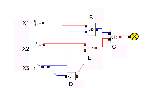
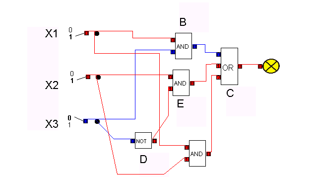
| 4.9 Programmable Logic Arrays (PLA´s) | ||||||||||||||||||||||||||||||||||||||||||||||||||||||||||||||||||||||||||||||||||||||||||||||||||||||||||||||||||||||||||||||||||||||||||||
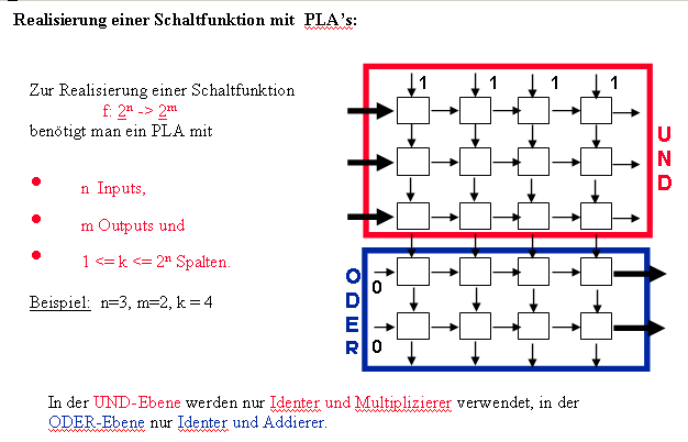
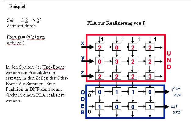
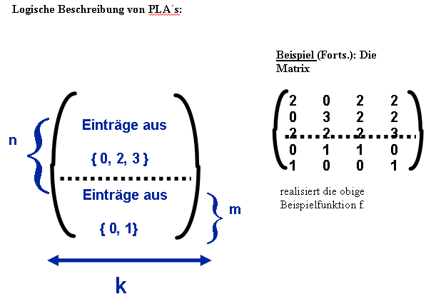
Programmable Logic Array (PLA) is an array of gates having interconnections that can be programmed
to perform a specific logical function. It has the following structure: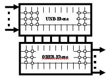
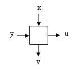
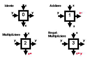
Inside PLA is wired in the form of grid, whereby there is a building block on the each point of intersection. Such a building block looks like:
The grid building blocks are defined with 0,1,2,3. The adder delivers on the "right"
output the sum of its inputs, the multiplier on "lower" output x*y bzw xy’.
|
||||||||||||||||||||||||||||||||||||||||||||||||||||||||||||||||||||||||||||||||||||||||||||||||||||||||||||||||||||||||||||||||||||||||||||