Grafikprogrammierung
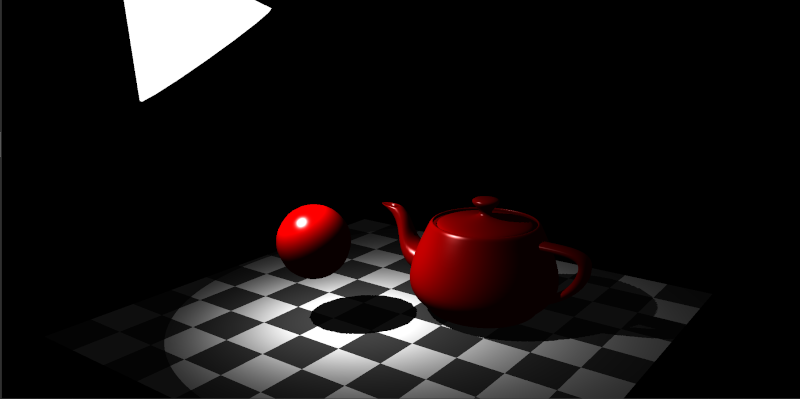
Schatten
Thorsten Thormählen
24. Januar 2025
Teil 11, Kapitel 1
Thorsten Thormählen
24. Januar 2025
Teil 11, Kapitel 1
Dies ist die Druck-Ansicht.
Weiterschalten der Folien durch die → Taste oder
durch das Klicken auf den rechten Folienrand.
Das Weiterschalten der Folien kann ebenfalls durch das Klicken auf den rechten bzw. linken Folienrand erfolgen.
| Typ | Schriftart | Beispiele |
|---|---|---|
| Variablen (Skalare) | kursiv | $a, b, x, y$ |
| Funktionen | aufrecht | $\mathrm{f}, \mathrm{g}(x), \mathrm{max}(x)$ |
| Vektoren | fett, Elemente zeilenweise | $\mathbf{a}, \mathbf{b}= \begin{pmatrix}x\\y\end{pmatrix} = (x, y)^\top,$ $\mathbf{B}=(x, y, z)^\top$ |
| Matrizen | Schreibmaschine | $\mathtt{A}, \mathtt{B}= \begin{bmatrix}a & b\\c & d\end{bmatrix}$ |
| Mengen | kalligrafisch | $\mathcal{A}, B=\{a, b\}, b \in \mathcal{B}$ |
| Zahlenbereiche, Koordinatenräume | doppelt gestrichen | $\mathbb{N}, \mathbb{Z}, \mathbb{R}^2, \mathbb{R}^3$ |
$\tilde{\underline{\mathbf{P}}} = \begin{pmatrix}\tilde{x}\\ \tilde{y} \\ \tilde{z} \\ \tilde{w} \end{pmatrix} \in \mathbb{H}^3 \quad \longmapsto \quad \tilde{\mathbf{P}} = \begin{pmatrix} \tilde{p}_x\\ \tilde{p}_y\\ \tilde{p}_z \end{pmatrix} = \begin{pmatrix}\frac{\tilde{x}}{\tilde{w}}\\\frac{\tilde{y}}{\tilde{w}}\\\frac{\tilde{z}}{\tilde{w}} \end{pmatrix} \in \mathbb{R}^3 $
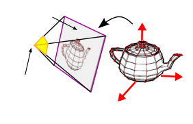
gluLookAt verwendet werden (siehe Teil 6, Kapitel 1)
gluLookAt(eyex, eyey, eyez, refx, refy, refz, upx, upy, upz);
gluPerspective generiert werden (siehe Teil 6, Kapitel 1)
gluPerspective(fovy, aspect, near, far)
fovy $=\beta_{\tiny \mbox{outer}}$
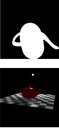
texture(shadowmap, vec2(s,t));
Vertex Shader :
#version 300 es
precision highp float;
precision highp int;

in vec3 position; // input vertex position from mesh
in vec2 texcoord; // input vertex texture coordinate from mesh
in vec3 normal;   // input vertex normal from mesh

uniform mat4 cameraLookAt; // camera look at matrix
uniform mat4 cameraProjection; // camera projection matrix
uniform mat4 spotLightTransform; // transformation matrix for the spot light
uniform mat4 meshTransform; // mesh transformation
uniform mat4 meshTransformTransposedInverse; // transposed inverse meshTransform
uniform mat4 shadowTransform; // shadow map transformation

out vec2 tc; // output texture coordinate of vertex
out vec3 wfn; // output fragment normal of vertex in world coordinate system
out vec3 vertPos; // output 3D position in world coordinate system
out vec4 shadowCoord; // output texture coordinate in shadow map

void main(){
  tc = texcoord;
  wfn = vec3(meshTransformTransposedInverse * vec4(normal, 0.0));
  vec4 vertPos4 = meshTransform * vec4(position, 1.0);
  vertPos = vec3(vertPos4) / vertPos4.w;

  //texture coordinates in shadow map
  shadowCoord = shadowTransform * vertPos4;

  gl_Position = cameraProjection * cameraLookAt * vertPos4;
}Fragment Shader :
#version 300 es
precision highp float;
precision highp int;
out vec4 outColor;
in vec2 tc; // texture coordinate of pixel (interpolated)
in vec3 wfn; // fragment normal of pixel (interpolated)
in vec3 vertPos; // fragment vertex position (interpolated)
in vec4 shadowCoord; // texture coordinate in shadow map (interpolated)
uniform int mode; // debug mode
uniform sampler2D diffuseTex; // diffuse texture
uniform float ambientFactor; // ambient factor
uniform vec4 specularColor; // specular color
uniform float shininess; // specular shininess exponent
uniform vec4 lightColor; // color of light
uniform vec3 lightPosition; // light position in world space
uniform vec3 lightDirection; // spot light direction in world space
uniform float lightCutoff; // spot light cut off
uniform float lightExponent; // spot light exponent
uniform float lightAttenuation; // quadratic light attenu.
uniform vec3 cameraPos; // camera position in world space
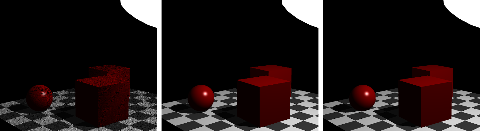
uniform float shadowBias; // shadow bias
uniform sampler2D shadowMap; // shadow map
vec3 blinnPhongBRDF(vec3 lightDir, vec3 viewDir, vec3 normal,
vec3 phongDiffuseCol, vec3 phongSpecularCol, float phongShininess) {
vec3 color = phongDiffuseCol;
vec3 halfDir = normalize(viewDir + lightDir);
float specDot = max(dot(halfDir, normal), 0.0);
color += pow(specDot, phongShininess) * phongSpecularCol;
return color;
}
vec3 blinnPhongShading(vec3 n, vec3 viewDir, vec3 lightDir, vec4 lightColor,
float lightAttenuation, vec4 diffuseColor, vec4 specColor,
float shininess, float ambientFactor)
{
// ambient Term
vec3 radiance = ambientFactor * diffuseColor.rgb;
// irradiance contribution from light
float irradiance = max(dot(lightDir, n), 0.0);
if(irradiance > 0.0) { // if receives light
vec3 brdf = blinnPhongBRDF(lightDir, viewDir, n,
diffuseColor.rgb, specColor.rgb, shininess);
radiance += brdf * irradiance * lightColor.rgb * lightAttenuation;
}
return radiance;
}
void main() {
vec3 lightVec = lightPosition - vertPos;
float d = length(lightVec); // distance to light
vec3 lightDir = normalize(lightVec);
vec3 normal = normalize(wfn.xyz);
vec3 viewDir = normalize(cameraPos - vertPos);
// compute shadow;
vec4 shadowCoordDiv = shadowCoord / shadowCoord.w;
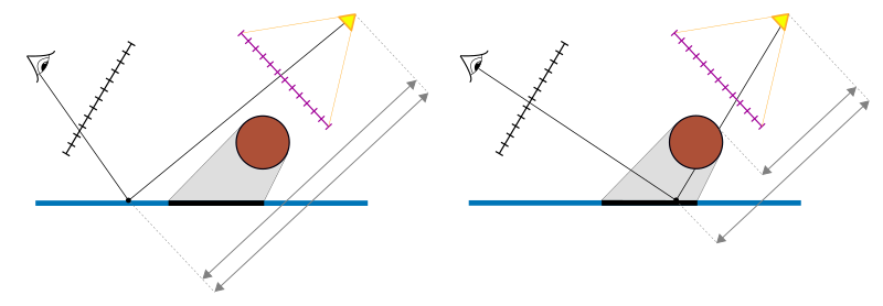
float nearestZ = texture(shadowMap, shadowCoordDiv.st).z;
float trueZ = shadowCoordDiv.z - shadowBias;
float shadowVal = nearestZ < trueZ ? 0.5 : 1.0;
float shadow = shadowVal;
if(dot(lightDir, normal) <= 0.0) {
shadow = 0.5;
}
// attenuation due to spot
float attenuation = abs(dot(lightDir, lightDirection));
if(attenuation < lightCutoff) {
attenuation = 0.0;
} else {
attenuation = pow(attenuation, lightExponent);
// atttenuation due to quadratic distance fall off
attenuation *= 1.0 / (lightAttenuation * d * d);
}
vec4 diffuseColor = texture(diffuseTex, tc);
vec4 color = ambientFactor * diffuseColor * lightColor;
color.a = 1.0;
if(shadow > 0.75) {
color.rgb = blinnPhongShading(normal, viewDir, lightDir,
lightColor, attenuation, diffuseColor, specularColor,
shininess, ambientFactor);
}
outColor = clamp(color, 0.0, 1.0);
}
Anregungen oder Verbesserungsvorschläge können auch gerne per E-mail an mich gesendet werden: Kontakt