Image Synthesis
Vulkan Ray Tracing Pipeline
Thorsten Thormählen
April 13, 2026
Part 2, Chapter 1
Thorsten Thormählen
April 13, 2026
Part 2, Chapter 1
This is the print version of the slides.
Advance slides with the → key or
by clicking on the right border of the slide
Slides can also be advanced by clicking on the left or right border of the slide.
| Type | Font | Examples |
|---|---|---|
| Variables (scalars) | italics | $a, b, x, y$ |
| Functions | upright | $\mathrm{f}, \mathrm{g}(x), \mathrm{max}(x)$ |
| Vectors | bold, elements row-wise | $\mathbf{a}, \mathbf{b}= \begin{pmatrix}x\\y\end{pmatrix} = (x, y)^\top,$ $\mathbf{B}=(x, y, z)^\top$ |
| Matrices | Typewriter | $\mathtt{A}, \mathtt{B}= \begin{bmatrix}a & b\\c & d\end{bmatrix}$ |
| Sets | calligraphic | $\mathcal{A}, B=\{a, b\}, b \in \mathcal{B}$ |
| Number systems, Coordinate spaces | double-struck | $\mathbb{N}, \mathbb{Z}, \mathbb{R}^2, \mathbb{R}^3$ |
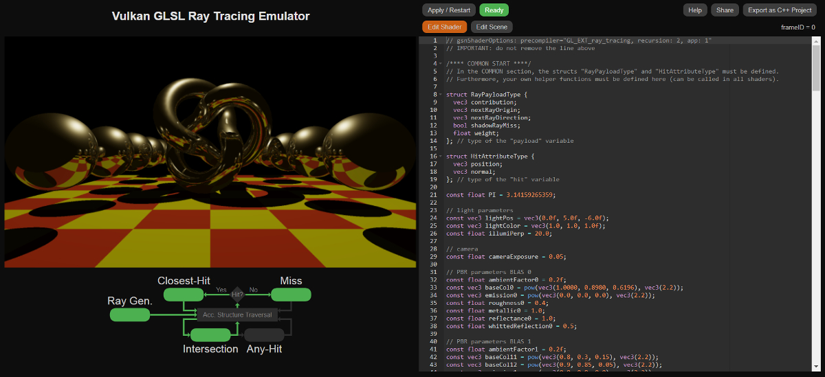

The ray tracing pipeline consists of 5 different shaders:
traceRayEXT(...)traceRayEXT function is the payload variable that
contains the collected information of the raypayload variable is of user-defined type and can be modified in the shaders stages that are called for a particular
ray during its traversaltraceRayEXT function returns to the caller and the
payload variable can be evaluated in the ray generation shader to produce an output image
reportIntersectionEXT(...)hitAttributeEXT variable (which can be of user-defined type).hitAttributeEXT vec2 baryCoord" variable
ignoreIntersectionEXT statementterminateRayEXT statementignoreIntersectionEXT statement
is not called in the shader, the hit is reported to the ray traversal
traceRayEXT function, which submits another ray into the
ray traversal block and might create a recursion | Ray generation | Closest-hit | Miss | Intersection | Any-hit | |
uvec3 gl_LaunchIDEXT |
✓ | ✓ | ✓ | ✓ | ✓ |
uvec3 gl_LaunchSizeEXT |
✓ | ✓ | ✓ | ✓ | ✓ |
int gl_PrimitiveID |
✓ | ✓ | ✓ | ||
int gl_InstanceID |
✓ | ✓ | ✓ | ||
int gl_InstanceCustomIndexEXT |
✓ | ✓ | ✓ | ||
int gl_GeometryIndexEXT |
✓ | ✓ | ✓ | ||
vec3 gl_WorldRayOriginEXT |
✓ | ✓ | ✓ | ✓ | |
vec3 gl_WorldRayDirectionEXT |
✓ | ✓ | ✓ | ✓ | |
vec3 gl_ObjectRayOriginEXT |
✓ | ✓ | ✓ | ||
vec3 gl_ObjectRayDirectionEXT |
✓ | ✓ | ✓ | ||
float gl_RayTminEXT |
✓ | ✓ | ✓ | ✓ | |
float gl_RayTmaxEXT |
✓ | ✓ | ✓ | ✓ | |
uint gl_IncomingRayFlagsEXT |
✓ | ✓ | ✓ | ✓ | |
float gl_HitTEXT |
✓ | ✓ | |||
uint gl_HitKindEXT |
✓ | ✓ | |||
mat4x3 gl_ObjectToWorldEXT |
✓ | ✓ | ✓ | ||
mat4x3 gl_WorldToObjectEXT |
✓ | ✓ | ✓ |
const uint gl_RayFlagsNoneEXT = 0u; |
const uint gl_RayFlagsNoOpaqueEXT = 2u; |
const uint gl_RayFlagsTerminateOnFirstHitEXT = 4u; |
const uint gl_RayFlagsSkipClosestHitShaderEXT = 8u; |
const uint gl_RayFlagsCullBackFacingTrianglesEXT = 16u; |
const uint gl_RayFlagsCullFrontFacingTrianglesEXT = 32u; |
const uint gl_RayFlagsCullOpaqueEXT = 64u; |
const uint gl_RayFlagsCullNoOpaqueEXT = 128u; |
const uint gl_HitKindFrontFacingTriangleEXT = 0xFEu; |
const uint gl_HitKindBackFacingTriangleEXT = 0xFFu; |
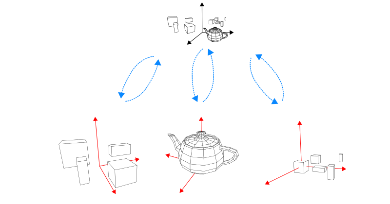
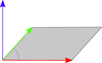
gl_ObjectToWorldEXTgl_WorldToObjectEXTgl_InstanceID = 0gl_InstanceID = 1gl_InstanceID = 2gl_InstanceIDgl_PrimitiveIDgl_ObjectToWorldEXT and
gl_WorldToObjectEXT variables


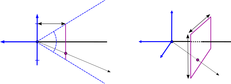
$\frac{f}{1} = \frac{\cos( 0.5 \, \Theta)}{\sin( 0.5 \, \Theta)} \Leftrightarrow f = \mathrm{cotan}( 0.5 \, \Theta)$
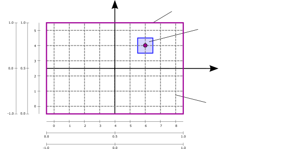
// Returns a camera ray for a camera at the origin that is
// looking in negative z-direction. "fieldOfViewY" must be given in degrees.
// "point" must be in range [0.0, 1.0] to cover the complete image plane.
//
vec3 getCameraRay(float fieldOfViewY, float aspectRatio, vec2 point) {
  // compute focal length from given field-of-view
  float focalLength = 1.0 / tan(0.5 * fieldOfViewY * 3.14159265359 / 180.0);
  // compute position in the camera's image plane in range [-1.0, 1.0]
  vec2 pos = 2.0 * (point - 0.5);
  return normalize(vec3(pos.x * aspectRatio, pos.y, -focalLength));
}

void main() { /**** RAY GENERATION SHADER ****/

  // compute the texture coordinate for the output image in range [0.0, 1.0]
  vec2 texCoord = (vec2(gl_LaunchIDEXT.xy) + 0.5) / vec2(gl_LaunchSizeEXT.xy);

  // camera's aspect ratio
  float aspect = float(gl_LaunchSizeEXT.x) / float(gl_LaunchSizeEXT.y);

  vec3 rayOrigin = vec3(0.0, 0.0, 0.0);
  vec3 rayDirection = getCameraRay(45.0, aspect, texCoord);
  ...
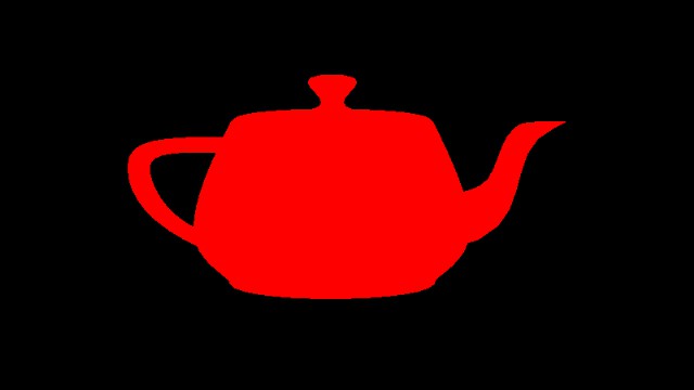

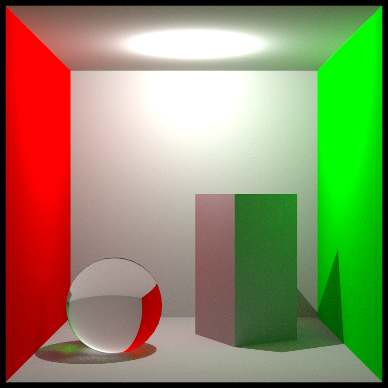
traceRayEXT(...) function in the ray generation shaderpayload.color variable is set to red.
Otherwise, if no hits occur, the miss shader is called and the payload.color variable is set to black.traceRayEXT function
returns to the calling ray generation shader and the modified payload.color variable
is written to the output image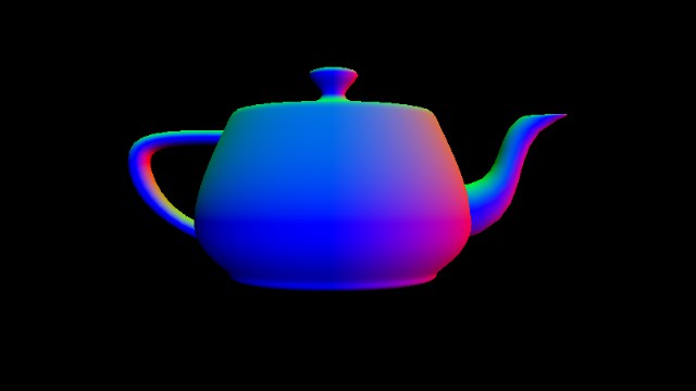
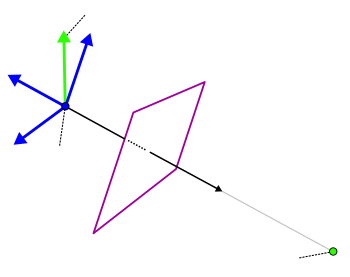
gl_InstanceID,
gl_ObjectToWorldEXT, and gl_PrimitiveID
are set accordingly and allow to identify the BLAS instance, its transformation, and the primitive (i.e., in this case, the triangle) of the closest hit location
gl_InstanceID and gl_PrimitiveID
variables as input parameters and return the local vertex positions, local normals, and texture coordinates for
the three vertices of the triangle that were hitvec2 baryCoord variable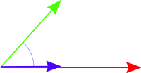

traceRayEXT function to submit a ray into the
acceleration structure traversal traceRayEXT to send a shadow ray in the direction of the light source.
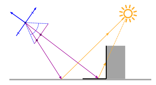
gl_RayFlagsSkipClosestHitShaderEXTgl_RayFlagsTerminateOnFirstHitEXT flag.payload.shadowRayMiss variable from false to truetraceRayEXT function returns to the emitting closest-hit shader,
this variable can be checked to determine if the surface point is in shadow or not
struct RayPayloadType {
  vec3 color;
  bool shadowRayMiss;
}; // type of the "payload" variable

...

void  main() { /**** CLOSEST-HIT SHADER ****/

  // get mesh vertex data in object space
  vec3 p0, p1, p2;
  gsnGetPositions(gl_InstanceID, gl_PrimitiveID, p0, p1, p2);
  vec3 n0, n1, n2;
  gsnGetNormals(gl_InstanceID, gl_PrimitiveID, n0, n1, n2);
  vec2 t0, t1, t2;
  gsnGetTexCoords(gl_InstanceID, gl_PrimitiveID, t0, t1, t2);

  // interpolate with barycentric coordinate
  vec3 barys = vec3(1.0f - baryCoord.x - baryCoord.y, baryCoord.x, baryCoord.y);
  vec3 localNormal = normalize(n0 * barys.x + n1 * barys.y + n2 * barys.z);
  vec3 localPosition = p0 * barys.x + p1 * barys.y + p2 * barys.z;
  vec2 texCoords = t0 * barys.x + t1 * barys.y + t2 * barys.z;

  // transform to world space
  mat3 normalMat;
  gsnGetNormal3x3Matrix(gl_InstanceID, normalMat);
  vec3 normal = normalize(normalMat * localNormal);
  vec3 position = gl_ObjectToWorldEXT * vec4(localPosition, 1.0);

  // dynamic light location
  float t = float(frameID % 45)/float(45);
  vec3 lightPos = vec3(5.0 * sin(2.0*PI*t), 5.0 * cos(2.0*PI*t),  5.0);
  vec3 lightDir = normalize(lightPos - position);

  // prepare shadow ray
  uint rayFlags = gl_RayFlagsTerminateOnFirstHitEXT |
                                gl_RayFlagsSkipClosestHitShaderEXT;
  float rayMin     = 0.001;
  float rayMax     = length(lightPos - position);
  float shadowBias = 0.001;
  uint cullMask = 0xFFu;
  float frontFacing = dot(-gl_WorldRayDirectionEXT, normal);
  vec3 shadowRayOrigin = position + sign(frontFacing) * shadowBias * normal;
  vec3 shadowRayDirection = lightDir;
  payload.shadowRayMiss = false;

  // shot shadow ray
  traceRayEXT(topLevelAS, rayFlags, cullMask, 0u, 0u, 0u,
         shadowRayOrigin, rayMin, shadowRayDirection, rayMax, 0);

  // diffuse shading
  vec3 radiance = ambientColor; // ambient term
  if(payload.shadowRayMiss) { // if not in shadow
    float irradiance = max(dot(lightDir, normal), 0.0);
    if(irradiance > 0.0) { // if receives light
      radiance += baseColor * irradiance; // diffuse shading
    }
  }

  payload.color = vec3(radiance);
}

void main() { /**** MISS SHADER ****/
  // set color to black
  payload.color = vec3(0.0, 0.0, 0.0);
  // shadow ray has not hit an object
  payload.shadowRayMiss = true;
}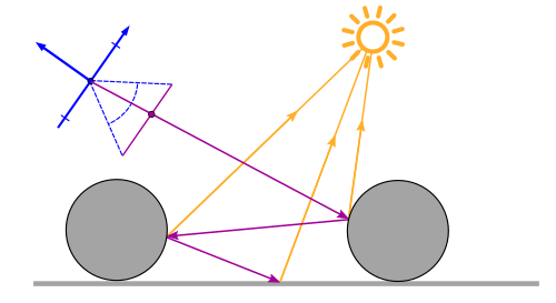
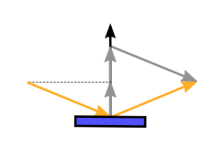
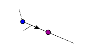
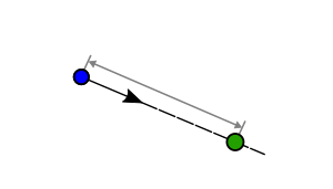
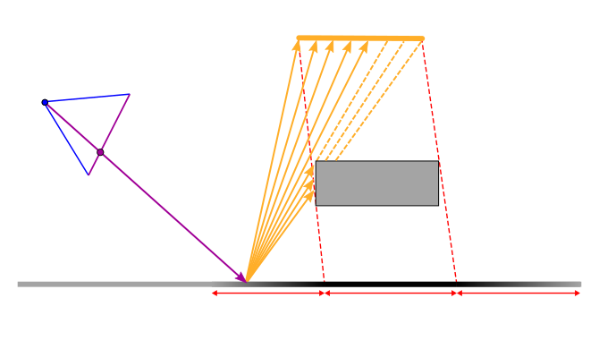
reflect to calculate the reflection direction:
vec3 r_out = reflect(r_in, normal);
trace(level, ray, &color) { // THIS IS PSEUDOCODE!!!
  if (intersect(ray, &hit)) {
    shadow = testShadow(hit);
    directColor = getDirectLight(hit, shadow);
    if (reflectionFactor > 0.0 && level < maxLevel) {
      reflectedRay = reflect(ray, hit.normal);
      trace(level + 1, reflectedRay, &reflectionColor); // recursion
    }
    color = color + directColor + reflectionFactor * reflectionColor;
  } else {
    color = backgroundColor;
  }
}
trace(ray, &color) { // THIS IS PSEUDOCODE!!!
  nextRay = ray;
  contribution = 1.0; level = 0;
  while (nextRay && level < maxLevel) {
    if (intersect(nextRay, &hit)) {
      shadow = testShadow(hit);
      directColor = getDirectLight(hit, shadow);
      if (reflectionFactor > 0.0) {
        reflectedRay = reflect(nextRay, hit.normal);
        nextRay = reflectedRay;
      } else {
        nextRay = false;
      }
    } else {
      directColor = backgroundColor;
      nextRay = false;
    }
    color = color + contribution * directColor;
    contribution = contribution * reflectionFactor;
    level = level + 1;
  }
}
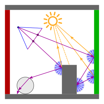
struct RayPayloadType {
vec3 directLight;
vec3 nextRayOrigin;
vec3 nextRayDirection;
float nextReflectionFactor;
bool shadowRayMiss;
}; // type of the "payload" variable
...
void main() { /**** RAY GENERATION SHADER ****/
// compute the texture coordinate for the output image in range [0.0, 1.0]
vec2 texCoord = (vec2(gl_LaunchIDEXT.xy) + 0.5) / vec2(gl_LaunchSizeEXT.xy);
// camera parameter
float aspect = float(gl_LaunchSizeEXT.x) / float(gl_LaunchSizeEXT.y);
vec3 rayOrigin = camPos;
vec3 rayDirection = getCameraRayLookAt(20.0, aspect, camPos,
camLookAt, camUp, texCoord);
uint rayFlags = gl_RayFlagsNoneEXT; // no ray flags
float rayMin = 0.001; // minimum ray distance for a hit
float rayMax = 10000.0; // maximum ray distance for a hit
uint cullMask = 0xFFu; // no culling
// init ray and payload
payload.nextRayOrigin = rayOrigin;
payload.nextRayDirection = rayDirection;
payload.nextReflectionFactor = 1.0;
float contribution = 1.0;
vec3 color = vec3(0.0, 0.0, 0.0);
int level = 0;
const int maxLevel = 5;
// shot rays
while(length(payload.nextRayDirection) > 0.1 &&
level < maxLevel && contribution > 0.001) {
// Submitting the camera ray to the acceleration structure traversal.
// The last parameter is the index of the "payload" variable (always 0)
traceRayEXT(topLevelAS, rayFlags, cullMask, 0u, 0u, 0u,
payload.nextRayOrigin, rayMin, payload.nextRayDirection, rayMax, 0);
color += contribution * payload.directLight;
contribution *= payload.nextReflectionFactor;
level++;
}
gsnSetPixel(vec4(color, 1.0));
}
void main() { /**** CLOSEST-HIT SHADER ****/
// get mesh vertex data in object space
vec3 p0, p1, p2;
gsnGetPositions(gl_InstanceID, gl_PrimitiveID, p0, p1, p2);
vec3 n0, n1, n2;
gsnGetNormals(gl_InstanceID, gl_PrimitiveID, n0, n1, n2);
vec2 t0, t1, t2;
gsnGetTexCoords(gl_InstanceID, gl_PrimitiveID, t0, t1, t2);
// interpolate with barycentric coordinate
vec3 barys = vec3(1.0f - baryCoord.x - baryCoord.y, baryCoord.x, baryCoord.y);
vec3 localNormal = normalize(n0 * barys.x + n1 * barys.y + n2 * barys.z);
vec3 localPosition = p0 * barys.x + p1 * barys.y + p2 * barys.z;
vec2 texCoords = t0 * barys.x + t1 * barys.y + t2 * barys.z;
// transform to world space
mat3 normalMat;
gsnGetNormal3x3Matrix(gl_InstanceID, normalMat);
vec3 normal = normalize(normalMat * localNormal);
vec3 position = gl_ObjectToWorldEXT * vec4(localPosition, 1.0);
vec3 lightDir = normalize(lightPos - position);
// prepare shadow ray
uint rayFlags = gl_RayFlagsTerminateOnFirstHitEXT |
gl_RayFlagsSkipClosestHitShaderEXT;
float rayMin = 0.001;
float rayMax = length(lightPos - position);
float shadowBias = 0.001;
uint cullMask = 0xFFu;
float frontFacing = dot(-gl_WorldRayDirectionEXT, normal);
vec3 shadowRayOrigin = position + sign(frontFacing) * shadowBias * normal;
vec3 shadowRayDirection = lightDir;
payload.shadowRayMiss = false;
// shot shadow ray
traceRayEXT(topLevelAS, rayFlags, cullMask, 0u, 0u, 0u,
shadowRayOrigin, rayMin, shadowRayDirection, rayMax, 0);
// diffuse shading (direct light)
vec3 radiance = ambientColor; // ambient term
if(payload.shadowRayMiss) { // if not in shadow
float irradiance = max(dot(lightDir, normal), 0.0);
if(irradiance > 0.0) { // if receives light
radiance += baseColor * irradiance; // diffuse shading
}
}
payload.directLight = radiance;
// compute reflected ray (prepare next traceRay)
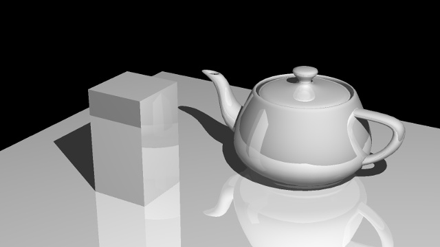
float reflectionFactor = 0.25;
if(reflectionFactor > 0.0) {
payload.nextRayOrigin = position;
payload.nextRayDirection = reflect(gl_WorldRayDirectionEXT, normal);
payload.nextReflectionFactor = reflectionFactor;
} else {
// no more reflections
payload.nextRayOrigin = vec3(0.0, 0.0, 0.0);
payload.nextRayDirection = vec3(0.0, 0.0, 0.0);
}
}
void main() { /**** MISS SHADER ****/
// set color to black
payload.directLight = vec3(0.0, 0.0, 0.0);
// shadow ray has not hit an object
payload.shadowRayMiss = true;
// no more reflections
payload.nextRayOrigin = vec3(0.0, 0.0, 0.0);
payload.nextRayDirection = vec3(0.0, 0.0, 0.0);
}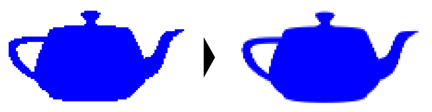
vec4 previousAverage = gsnGetPreviousPixel();
vec3 newAverage = (previousAverage.rgb * float(frameID) + payload.color) / float(frameID + 1);
gsnSetPixel(vec4(newAverage, 1.0));

| Index $n$ | Numerical value (Base 2) | Mirrored | $h_2(n)$ |
|---|---|---|---|
| 1 | 1 | 0.1 = 1/2 | 0.5 |
| 2 | 10 | 0.01 = 1/4 | 0.25 |
| 3 | 11 | 0.11 = 3/4 | 0.75 |
| 4 | 100 | 0.001 = 1/8 | 0.125 |
| 5 | 101 | 0.101 = 1/2 + 1/8 | 0.625 |
| 6 | 110 | 0.011 = 1/4 + 1/8 | 0.375 |
| 7 | 111 | 0.111 = 1/2 + 1/4 + 1/8 | 0.875 |

| Index $n$ | Numerical value (Base 3) | Mirrored | $h_3(n)$ |
|---|---|---|---|
| 1 | 1 | 0.1 = 1/3 | 0.333 |
| 2 | 2 | 0.2 = 2/3 | 0.666 |
| 3 | 10 | 0.01 = 1/9 | 0.111 |
| 4 | 11 | 0.11 = 1/3 + 1/9 | 0.444 |
| 5 | 12 | 0.21 = 2/3 + 1/9 | 0.777 |
| 6 | 20 | 0.02 = 2/9 | 0.222 |
| 7 | 21 | 0.12 = 1/3 + 2/9 | 0.555 |
| 8 | 22 | 0.22 = 2/3 + 2/9 | 0.888 |


Please notify me by e-mail if you have questions, suggestions for improvement, or found typos: Contact