Control Keys

move to next slide (also Enter or Spacebar).
move to previous slide.
 d  enable/disable drawing on slides
 p  toggles between print and presentation view
CTRL  +  zoom in
CTRL  -  zoom out
CTRL  0  reset zoom

Slides can also be advanced by clicking on the left or right border of the slide.

Notation

Type Font Examples
Variables (scalars) italics $a, b, x, y$
Functions upright $\mathrm{f}, \mathrm{g}(x), \mathrm{max}(x)$
Vectors bold, elements row-wise $\mathbf{a}, \mathbf{b}= \begin{pmatrix}x\\y\end{pmatrix} = (x, y)^\top,$ $\mathbf{B}=(x, y, z)^\top$
Matrices Typewriter $\mathtt{A}, \mathtt{B}= \begin{bmatrix}a & b\\c & d\end{bmatrix}$
Sets calligraphic $\mathcal{A}, B=\{a, b\}, b \in \mathcal{B}$
Number systems, Coordinate spaces double-struck $\mathbb{N}, \mathbb{Z}, \mathbb{R}^2, \mathbb{R}^3$

Digitization of Audio

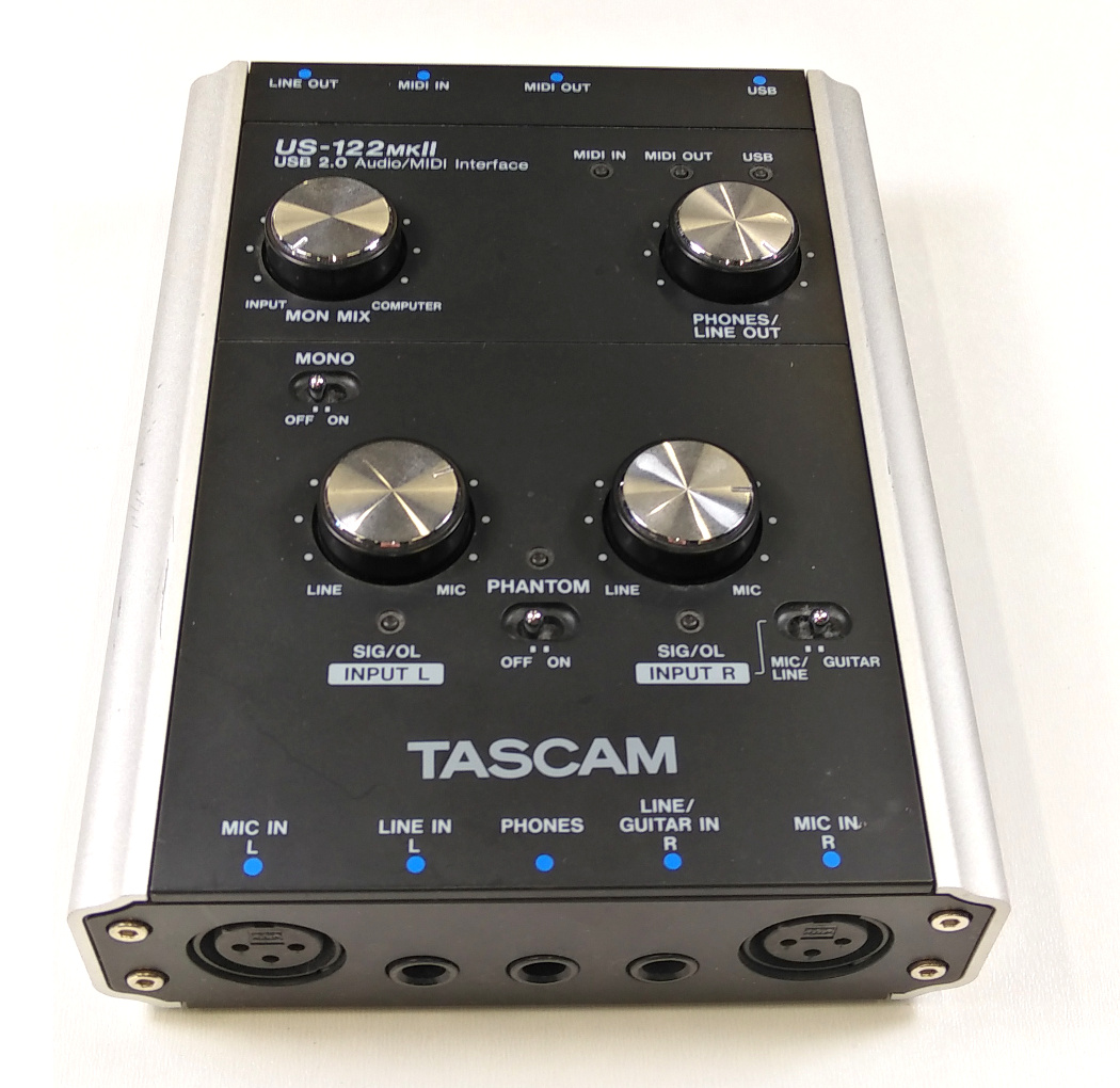
audio_interface_tascam

Sound Propagation

  • A sound source (such as our voice, an instrument, or a passing car) sets an elastic medium (such as air or water) in motion
  • This causes a wave propagation in which the direction of oscillation corresponds to the direction of propagation (longitudinal wave)
  • Analogy: Stone falls into water
  • The propagation speed of the sound wave (speed of sound) in air is 343,2 m/s or 1236 km/h
  • Effects such as absorption, reflection, scattering, diffraction, etc. can occur

The Human Ear

anatomy_ear
Stirrup
Anvil
Hammer
Semicircular canals
Hearing nerve
Cochlea
Ear canal
Auricle
Eardrum
16 kHz
6 kHz
0.5 kHz

The Human Ear

  • The sound wave hits the eardrum and is mechanically amplified via the anvil, hammer and stirrup and transmitted to the cochlea
  • Depending on the frequency of the sound wave, a resonance forms in a certain area in the liquid-filled chambers of cochlea (high frequencies at the beginning and low frequencies at the end of the channel)
  • The hair cells on the basilar membrane along the cochlear canal are mechanically stimulated and transmit the information via the auditory nerve to the auditory cortex in the brain
  • The ear therefore performs a kind of frequency transformation
  • The audible frequency range is from around 20 Hz to 20 kHz (depending on age)
  • The hair cells can be irreparably damaged by high sound stress (amplitude and duration of exposure)

Sound Pressure Level

  • The sound pressure level (SPL) is commonly used to measure the volume of certain sounds
  • The sound pressure level $L_p$ can be calculated from the logarithmic ratio of the RMS value of the sound pressure waves $\bar{p}_{\mathrm{rms}}$ and the reference value of the hearing threshold $\bar{p}_0$ of the human ear at a frequency of 1 kHz:
    $L_p = 20 \log\left(\frac{\bar{p}_{\mathrm{rms}}}{\bar{p}_0}\right) \mathrm{dB}$
  • The sound pressure level uses the pseudo unit decibel (dB)
  • Damage to the ear occurs from approx. 120 dB for short-term exposure and from approx. 85 dB for long-term exposure
Sound: Rifle Trumpet Nightclub TV Conversation Leaf rustling
Distance: 1 m 0.5 m 1 m 1 m 1 m at the ear
Sound pressure level:170 dB130 dB 100 dB 60 dB 40-60 dB10 dB
Quelle: Wikipedia

Reference values for decibel specifications

audiolevel
  • In audio systems, the pseudo-unit decibel is used for various things. It always depends on the reference value. Some examples:
    • The signal-to-noise ratio is the ratio between signal and noise power:
      $\mathrm{SNR} = 20 \log\left(\frac{\bar{p}_{\mathrm{signal}}}{\bar{p}_{\mathrm{noise}}}\right) \mathrm{dB}$
    • dBFS: Ratio of the current amplitude to the maximum amplitude (decibels relative to full scale). With a digital 16-bit audio signal, a maximum amplitude of +32767 to -32768 is possible:
      $20 \log\left(\frac{|A|}{32768}\right) \mathrm{dBFS}$
      0 dBFS is the maximum amplitude, -6 dBFS half the maximum amplitude, -12 dBFS a quarter of the maximum amplitude and so on

      For signal levels above 0 dBFS, clipping occurs with digital audio signals (limitation to the maximum value). Therefore, 0 dBFS should not be exceeded.

Microphones

  • A microphone converts sound pressure waves into an analog electrical voltage
  • Typically, the movement of a thin membrane is measured, which is driven by the sound pressure wave
  • Important characteristics of a microphone are its frequency response and polar pattern
frequency_response_shure_sm58
Frequency Response
Polar Pattern

Dynamic Microphones

dynamic_microphone
Moving Coil Microphone
  • With dynamic microphones, it is not the displacement of the diaphragm that is measured, but its change in position (speed)
  • A widely used, robust and cost-effective design is the moving coil microphone (see image)
  • The movement of the coil in the magnetic field of a permanent magnet causes an induction of voltage
  • An external power supply is not required
  • Since the diaphragm is connected to the coil, both must be moved by the sound pressure waves, which is why moving coil microphones do not reproduce high frequencies so well
  • Particularly suitable for loud sound sources (such as live singing or wind instruments)

Condenser Microphone

condenser_microphone
Condenser Microphone
  • In a condenser microphone, a thin conductive diaphragm is used as one plate of a plate condenser
  • Changing the position of the diaphragm changes the capacitance of the capacitor
  • By connecting a voltage source and a parallel high-impedance resistor, the capacitance change of the capacitor can be converted into a voltage change
  • However, the output voltage cannot be used directly. A impedance converter (amplifier circuit) is required within the microphone.
  • Since condenser microphones require a power source, they must be powered either by batteries or a 48-volt phantom power supply from the mixer/audio interface
  • Due to the low mass of the diaphragm, condenser microphones are very sensitive (good for high-frequency signals and distant sound sources)
  • Because of their good sound quality, they are particularly popular for studio recordings (since external noise can be avoided in a studio)

Unbalanced and balanced signal transmission

  • When wiring instruments and microphones to the mixing console or audio interface, long cables are often used. Long cables are sensitive to noise and interference.
  • For unbalanced transmission of a mono audio signal, only two lines (ground and signal) are required
  • As the ground of all devices is connected, it is the common potential reference point. If there is interference on a cable, the interference may become audible.
  • For balanced transmission of a mono audio signal, three lines are used (hot, cold and ground)
  • At the audio source, the inverted hot signal is used as the cold signal
  • At the receiver, the difference is formed and thus additive errors are eliminated
symmetric audio
Signal
Ground
Hot
Cold
Ground
unbalanced
balanced
Differential amplifier

Audio Cables

anatomy_ear
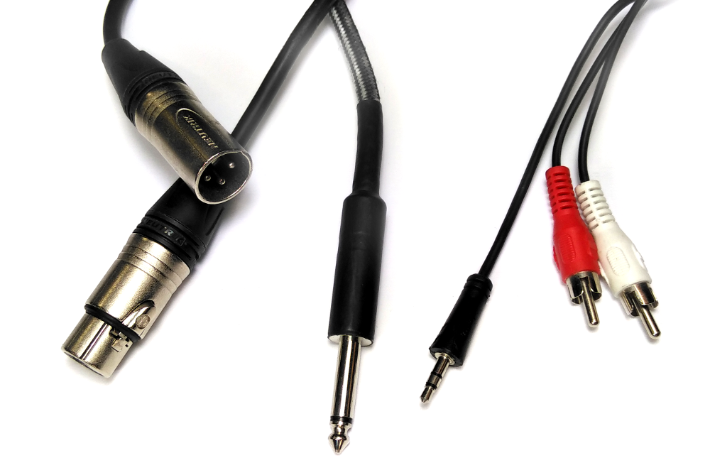
XLR connector male
XLR connector female
1⁄4 Inch Jack (Tip, Sleeve)
⅛ Inch Jack (Tip, Ring, Sleeve)
RCA connector

Audio Cables

  • XLR plugs and sockets are often used for balanced audio transmission
  • Jack plugs are available in different sizes:
    • 6,3 mm (1⁄4 Inch Jack)
    • 3,5 mm (⅛ Inch Jack)
    • 2.5 mm (⅒ Inch Jack)
  • Jack plugs are available in mono (ground and signal) or stereo versions (ground, left and right channel)
  • Jack plugs and jack sockets are typically used for unbalanced audio transmission
  • But beware: a few audio devices also use stereo jacks for balanced mono audio transmission
  • RCA plugs and sockets are used for unbalanced audio transmission (typically line level)

Audio Cable and Signal Level

  • Microphone level: Weakest signal with amplitudes of a few millivolts
    • The audio signal is typically transmitted to the audio interface/mixing console using balanced XLR cables
  • Instrument level: between microphone and line level
    • E.g. the output signal of an electric guitar
    • Signal is typically transmitted unbalanced via jack cable
  • Line level: Amplitudes from approx. 0.5 to a maximum of 2.0 volts:
    • This level is typically expected from the audio systems
    • Microphone level and instrument level must be increased to line level by a preamplifier
    • dBu: Here the reference value is an effective value of 0.775 V, i.e.
      $0 \,\mathrm{dBu}\, \mapsto 0.775\, \mathrm{V} $
    • dbV: Here the reference value is an effective value of 1 V, i.e.
      $0 \,\mathrm{dBV}\, \mapsto 1.0\, \mathrm{V} $

Analog-to-Digital Conversion within an Audio Interface

adc
analog signal
digital signal
Preamplifier
Anti-aliasing filter
Sample & Hold
Quantizer
sampling
Signal
Digitized signal
Time

Preamplifier

  • The task of the preamplifier is to adjust the amplitude of the input signal so that the available amplitude range of the digital signal is utilized as best as possible
  • The "leveling" of the preamplifier is usually carried out manually in the professional sector, as automatic approaches do not know what signal levels to expect
  • Level too high: Clipping occurs above 0 dbFS
  • Level too low: quantization noise is noticeable

Anti-Aliasing-Filter

  • To comply with the sampling theorem, an analog low-pass filter is used before sampling
  • The low-pass filter must be selected so that its cut-off frequency corresponds to half the sampling frequency $F_a$

Sample & Hold

  • The sample-and-hold circuit (see below) is used to keep the analogue input value constant during subsequent quantization
  • The electronic switch (transistor) is closed for a short time. The capacitor charges and adopts the current voltage value of the input signal (sample). The switch is then opened again.
  • When the switch is open, it is the capacitor's job to keep the voltage value constant (hold)
  • This process is repeated with the sampling frequency $F_a$
sampling
Operational amplifier
(Impedance converter)
Switch (Transistor)
F_a
C
Operational amplifier
Input signal
Output signal

Quantizer

  • Quantizers with at least 16-bit resolution are typically used for audio processing
  • Nowadays, A/D conversion in audio signal processing is therefore almost exclusively based on delta-sigma modulation
  • The idea is not to operate many analog comparator circuits in parallel (at 16 bits this would require 216 = 65536) but only one comparator operating at a multiple of the sampling frequency
  • The error of the comparator is added up in each time step until it is again above or below the decision threshold of the comparator
  • A subsequent digital counter can then determine how often the detection threshold was exceeded or missed in order to determine the quantized digital value
  • Example: With a sampling rate of 48000 Hz and a 16-bit resolution, the delta-sigma modulator must be operated at 48000 Hz · 216 = 3.15 GHz
  • A first-order delta sigma modulator is presented in the following. In practice, higher order delta sigma modulators (i.e. with several integration stages) are used, which have a better signal-to-noise ratio. However, the principle remains the same.

Quantizer: Delta-Sigma-Modulation

  • The analog comparator is a transistor circuit that implements the following function:
    $V_{\mathrm{out}}= \begin{cases} 1 & \,\,:\,\, V_{\mathrm{in}} \ge 0.0 \\ 0 & \,\,:\,\,V_{\mathrm{in}} < 0.0 \\ \end{cases}$
    where $1$ represents the value for the digital one.
  • The D-flip-flop (known from my Technical Computer Science lecture) realizes a delay of one clock cycle
  • The 1-bit D/A converter outputs:
    $V_{\mathrm{out}}= \begin{cases} V_{\mathrm{max}} & \,\,:\,\, V_{\mathrm{in}} \ge 0.5\\ -V_{\mathrm{max}} & \,\,:\,\,V_{\mathrm{in}} < 0.5\\ \end{cases}$
    where $0.5$ is the threshold value between the digital one and the digital zero.

Quantizer: Delta-Sigma-Modulation Example

Linear Pulse Code Modulation (LPCM)

  • The output of the quantizer is a so-called Pulse Code Modulation (PCM), i.e. a data stream of digital ones and zeros
  • With a 16-bit quantizer, 216 = 65536 different 16-bit binary code words are available, which can be assigned to the individual quantization levels
  • Signed numbers in two's complement are often used (see my Technical Computer Science lecture)
  • With the 16-bit two's complement, this gives a value range from +32767 to -32768

Linear Pulse Code Modulation (LPCM)

  • Example for 3-bit LPCM:
pcm
Serial
PCM Signal
Code Word
(Two's complement)

Linear Pulse Code Modulation (LPCM)

  • Audio CD
    • A signed 16-bit LPCM signal with a sampling rate of 44100 Hz is used for an audio CD ("Compact Disc Digital Audio")
    • In alternating sequence, 16 bits are written for the left channel and then 16 bits for the right channel
    • The effective data rate is therefore 2 · 16 bits · 44100 1/s = 1.41 MBit/s
  • DVD-Audio
    • Also uses a signed LPCM signal
    • Various quantizations are possible: 16 / 20 / 24 bits per sample
    • Various sampling rates: 44.1 / 48 / 88.2 / 96 / 176.4 / 192 kHz
    • 1 channel to 6 channels (maximum data rate: 9.6 MBit/s)
  • WAV Audio Files
    • The widely used WAV format ("Waveform Audio File Format") is a container that can contain various audio formats
    • In practice, WAV files usually contain uncompressed LPCM audio data

Non-Linear Pulse Code Modulation

  • PCM also works with non-linear quantization intervals
  • For this purpose, a compressor is inserted before the linear quantizer
  • The aim is to adapt to human hearing, which perceives quiet sounds more sensitively than loud sounds (logarithmic)
  • The amplitude range is divided into segments, each of which is then quantized linearly
  • Example: Digital telephone transmission (ISDN)
    • 1 bit sign, 3 bit segment, 4 bit quantization value
    • Sampling rate: 8 kHz
    • Data rate: 8 Bit · 8 kHz = 64 kBit/s
  • A corresponding expander must then be applied to the receiver side after the D/A conversion (as a counterpart to the compressor)
pcm
Anti-Aliasing Filter
(Low pass)
A/D Converter
D/A Converter
Compressor
Expander
Reconstruction Filter
(Low pass)
Transmitter
Receiver
Telephone channel

Non-Linear Pulse Code Modulation: Compressor

compressor
1 bit for sign
3 bits for segment code
4 bits per segment

Digital-to-Analog Conversion

pcm
Analog signal after low-pass filtering
Analog step function
Digital representation
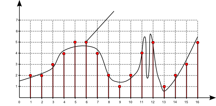
  • As known from the chapter “Sampling Theorem”, for a digital-to-analog conversion we would have have to convert the digital signal into anaologous Dirac pulses with a corresponding height and then apply a reconstruction filter (low-pass)
  • Of course, this is not feasible in an ideal way in practice
  • Instead, we could use a step function with a corresponding number of voltage levels, which is then smoothed with a reconstruction filter

Digital-to-Analog Conversion

  • Such an analog step function could be created with an resistor ladder, but for higher bit depths the accuracy of the resistors must be extremely high
  • Therefore, in practice, delta sigma modulators are also used for D/A conversion. They can be operated in the GHz range and generate a very high-frequency high-low analog signal that generates the desired analog audio signal when filtered with an analog low-pass filter (e.g., cut-off frequency 20 kHz)
pcm
Output of the delta-sigma modulation
Low pass
Analog signal

Are there any questions?

questions

Please notify me by e-mail if you have questions, suggestions for improvement, or found typos: Contact

More lecture slides

Slides in German (Folien auf Deutsch)