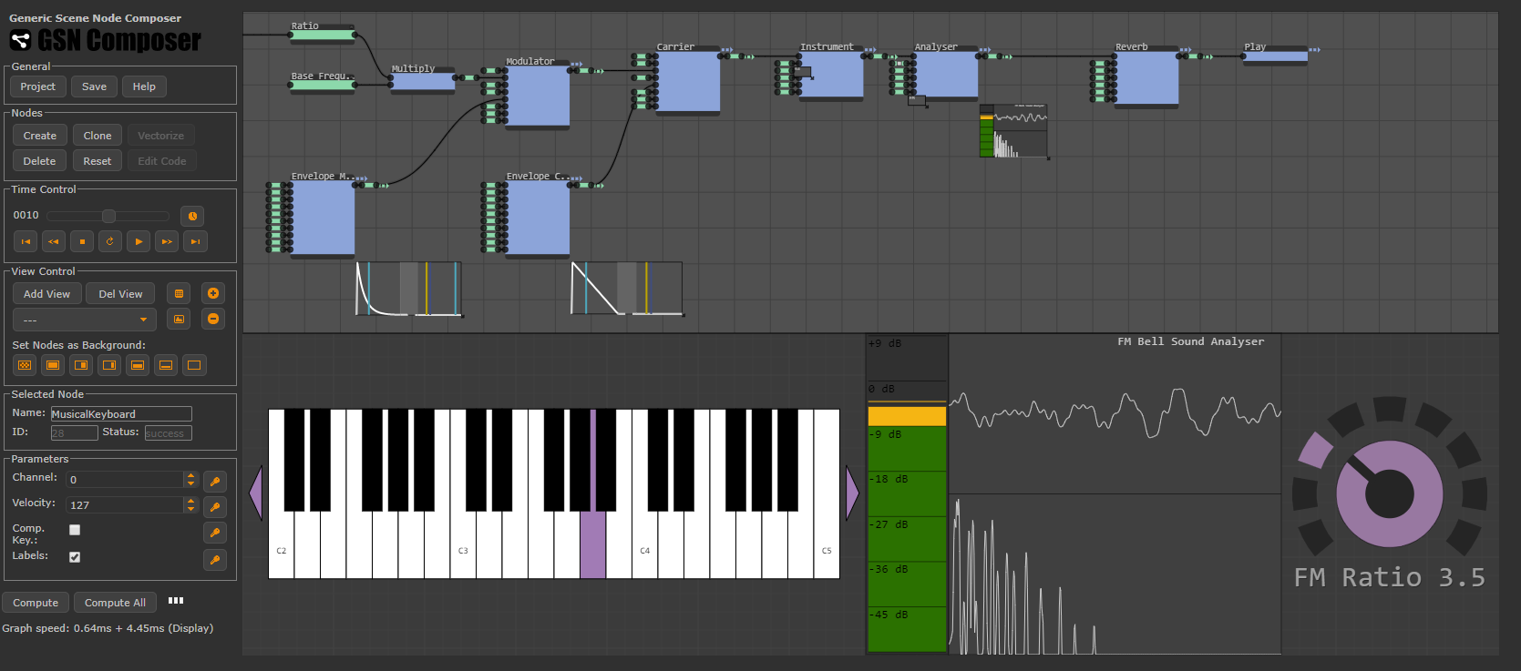
Control Keys

move to next slide (also Enter or Spacebar).
move to previous slide.
 d  enable/disable drawing on slides
 p  toggles between print and presentation view
CTRL  +  zoom in
CTRL  -  zoom out
CTRL  0  reset zoom

Slides can also be advanced by clicking on the left or right border of the slide.

Notation

Type Font Examples
Variables (scalars) italics $a, b, x, y$
Functions upright $\mathrm{f}, \mathrm{g}(x), \mathrm{max}(x)$
Vectors bold, elements row-wise $\mathbf{a}, \mathbf{b}= \begin{pmatrix}x\\y\end{pmatrix} = (x, y)^\top,$ $\mathbf{B}=(x, y, z)^\top$
Matrices Typewriter $\mathtt{A}, \mathtt{B}= \begin{bmatrix}a & b\\c & d\end{bmatrix}$
Sets calligraphic $\mathcal{A}, B=\{a, b\}, b \in \mathcal{B}$
Number systems, Coordinate spaces double-struck $\mathbb{N}, \mathbb{Z}, \mathbb{R}^2, \mathbb{R}^3$

Musical Tones and Overtones

Pitch

  • A musical tone of a certain pitch can be produced, for example, by a sine oscillation with a certain frequency
  • In 1939, at an international conference organized by the British Standards Institute the concert pitch was defined to be 440 Hz
  • With each further octave (e.g. from A3 to A4) the frequency doubles
piano

Pitch

  • Between two adjacent notes on a piano, the ratio $f_{x+1}/f_{x}$ of the frequencies is constant
  • With twelve keys per octave, the constraint that the frequency doubles per octave gives:
    $\frac{f_{x+1}}{f_x} = \sqrt[12]{2} = 1.059463$
  • I.e., for A#3 this results in $440\,\mbox{Hz} \cdot 1.059463 = 466.163\,\mbox{Hz}$
piano

Overtones

  • When a string (e.g. in a piano) is set into vibration, only very specific vibrations can occur, since the string is fixed at its start and end
  • The so-called fundamental frequency of the wavelength $W = 2 \, l$ is generated, if $l$ is the length of the string
  • But usually also so-called overtones occur with the following wavelength:
    $W = \frac{2 \, l}{k} \quad \forall \, k \in {2, 3, 4, 5, ....}$
  • string_spec
    Amplitude
    Frequency
    $f_1$
    $f_2$
    $f_3$
    $f_4$
    $f_5$
    A typical frequency spectrum, is shown on the right
  • For different instruments, the different overtones are amplified differently by their resonating bodies, resulting in their characteristic sounds

Temporal change of the involved frequencies

  • The following diagrams show the change over time of the amplitude of the fundamental (1st harmonic) and of 7 overtones (2nd to 8th harmonics) for three different instruments
instruments_harmonics
Piano
Trumpet
Violin

Subtractive Synthesis

Subtractive Synthesis of Sounds

  • The subtractive synthesis of sounds starts with a signal with many harmonics, such as a square wave or sawtooth wave
  • Overtones are removed from the spectrum of the original signal by filtering
  • E.g., low-pass, band-pass, high-pass, or band-stop filters can be used
  • Since such signals and filters could easily be realized with analog signal processing, subtractive synthesis could be used even before the advent of capable digital signal processors (in the 1960s and 1970s)

Subtractive Synthesis: Oscillators and their Spectrum

instruments_harmonics
Sinus Wavefront
Sinus Spectrum
Triangle Wavefront
Triangle Spectrum
Square Wavefront
Square Spectrum
Sawtooth Wavefront
Sawtooth Spectrum

Subtractive Synthesis: Filter

sub_synth
Frequency
Original Spectrum
Filtered Spectrum
Low-pass filter
High-pass filter
Band-pass filter
Band-stop filter

Subtractive Synthesis: Filter

  • Let $\mathrm{H}[u]$ be the spectrum of the filter and $\mathrm{F}[u]$ the spectrum of the original signal, then the filtered spectrum in the frequency domain can be generated by multiplying the two spectra
    $\mathrm{F}'[u] = \mathrm{F}[u] \,\,\mathrm{H}[u]$
  • However, to this end, a DFT (to generate $\mathrm{H}[u]$) and an IDFT (to generate the filtered signal in the time domain $\mathrm{f}'[n]$) must be performed
  • Therefore, in real-time processing, the filtering is typically always performed in the time domain
  • This can be achieved by convolving the original signal $\mathrm{f}[n]$ with the IDFT $\mathrm{h}[n]$ of the filter spectrum $\mathrm{H}[u]$:
    $\mathrm{f}'[n] = \mathrm{f}[n] \ast \mathrm{h}[n]$
  • However, filtering by convolution requires a relatively large amount of computation time
  • Therefore, so-called IIR filters (filters with feedback) are often used in sound synthesis because of their special sound properties and lower computational effort (more on this later)

Envelopes

  • An envelope can be used to change certain sound parameters over time
  • For example, to change the volume, the audio signal $x[n]$ can be multiplied by the envelope $\mathrm{A}[n]$:
    $x'[n] = \mathrm{A}[n] \, x[n]$
  • Applying such an envelope to the amplitude is called VCA (Voltage Controlled Amplifier) in analog synthesizers
  • However, other parameters can also be changed over time: e.g. the frequency of an oscillator (VCO = Voltage Controlled Oscillator) or the cutoff frequency and resonance of a filter (VCF = Voltage Controlled Filter)

Envelopes

  • To simulate the hitting of a key, ADSR envelopes are often used (Attack, Decay, Sustain, Release)
  • An ADSR envelope is typically defined by the following parameters:
envelop_generator
A[n]
n
Attack
Time
Decay
Time
Sustain Level
Release Time
  • When the key is pressed down, the attack and decay phases are executed and then the sustain value is held until the key is released and the release phase begins

LFO

  • An LFO (Low-frequency Oscillator) is another way to change sound parameters over time
  • As the name suggests, it is an oscillator that oscillates very slowly (< 20 Hz)
  • The output signal of an LFO has such a low frequency that it is no longer directly audible
  • Only by modulating an audio signal in the audible range the LFO becomes perceptible
  • For example:
    • Tremolo: Change of amplitude (VCA) via LFO
    • Vibrato: Changing the pitch of an oscillator (VCO) via LFO
    • Filter modulation: Changing the cutoff frequency or resonance of a filter (VCF)
    • Panorama: Changing the amplitude of the right and left channel of a stereo signal via an LFO

Example of a Subtractive Synthesizer

sub_synth
  • This simple synthesizer consists of two oscillators, three ADSR envelopes, an LFO and a filter. Try it out here: Cardboard Online Synth
  • If you want to play several notes at the same time, multiple instances of these components are required

Additive Synthesis

Additive Synthesis of Sounds

  • For the additive synthesis of sounds, a powerful digital signal processor is required
  • The signal is composed from the addition of multiple sine waves:
    $\mathrm{y}[n] = A_0 \sin(2 \pi f_0 n) + A_1 \sin(2 \pi f_1 n) + A_2 \sin(2 \pi f_2 n) + \dots$
    or for $N$ superpositions
    $\mathrm{y}[n] = \sum\limits_{u=0}^{N-1} A_u \sin(2 \pi \frac{u}{N} n)$
  • This calculation procedure strongly reminds us of the IDFT, and indeed, the additive synthesis can be realized by directly specifying Fourier coefficients $A_u$ and applying the IDFT

Example: Additive Synthesis of Sounds

additive_synth_example

Additive Synthesis of Sounds

  • Even more possibilities arise if the coefficients $A_u$ are time-varying, i.e.
    $\mathrm{y}[n] = \sum\limits_{u=0}^{N-1} A_u[n] \sin(2 \pi \frac{u}{N} n)$
  • Futhermore, with sufficient computing power, even the individual frequencies could be modified by a time-varying offset $d_u[n]$:
    $\mathrm{y}[n] = \sum\limits_{u=0}^{N-1} A_u[n] \sin(2 \pi \frac{u-d_u[n]}{N} n)$

Wavetable Synthesis

Wavetable

instruments_harmonics
  • The idea of wavetable synthesis is to generate sounds through a periodic waveform
  • Instead of generating the waveforms with a standard oscillator (sine, square, triangle, etc.), the samples for one period of the wave are pre-computed and stored in a "wavetable"
  • A wavetable can also be extracted from recordings of real instruments or be created from an additive synthesis
  • This allows for much more complex waveforms
  • Playing the waveform in a loop creates the specific sound
  • In order to create different pitches, a wavetable must be played at different speeds (by resampling it)

Multiple-Wavetable Synthesis

multi_wavetable
Wavetable 1
Wavetable 2
Wavetable 3
Envelope 1
Envelope 2
Envelope 3
Output
  • A time-varying additive superposition of multiple wavetables creates even more possibilities in sound synthesis
  • The variant shown above is called "wavetable stacking"
  • If only two wavetable oscillators are active at a time, this is called "Wavetable-Crossfading", "Wavetable-Interpolation" or "Wavetable-Morphing"

Multiple-Wavetable Synthesis: Wavetable-Crossfading

wavetable_interp
Source: Screenshot from WaveEdit

Sample-based Synthesis

Sample-based Synthesis of Sounds

  • In sample-based synthesis of sounds, pre-recorded or recorded tones of an instrument are simply played back
  • This technique is especially easy if there is a separate sample for each pitch (key on the keyboard)
  • Sometimes even separate samples for different velocities of the keys are recorded/provided
  • This is a very common method for reproducing real instruments
  • Ein Nachteil ist, dass der Klang im Nachhinein nicht stark veränderbar ist
  • Ein weiterer Nachteil ist der hohe Speicherbedarf
  • If memory has to be saved, it is not possible to provide a sample for each pitch. Instead we could use, for example, only one sample per octave. This sample must then be converted to the correct pitch by playing it back at a correspondingly higher or lower speed (→ Resampling)

Example: Sample-based Synthesis of Sounds

gsn_piano

Upsampling

  • If the sampling rate has to be increased by a constant integer factor $L$, first $L-1$ zeros are inserted between the existing samples
  • Then a low pass is applied to the resulting signal
  • What cutoff frequency must be set for the low-pass filter?
  • Since we can assume that the sampling theorem was observed for the original signal, i.e. the maximum frequency in the signal corresponds to half the orginal sampling frequency, the cutoff frequency of the low-pass filter must be set to half the original sampling frequency

Upsampling

  • An ideal low-pass filter in the time domain can be achieved by convolution with a sinc function of infinite length
  • If the sinc function is chosen as follows, it will have its zero crossings exactly at the original sample positions:
    $\mathrm{h}[n] = \operatorname{sinc}[n] = \frac{\sin(\pi \, n / L)}{n}$
  • This means, the original values are not changed by the low pass filtering
upsample_with_si
$\mathrm{h}[n]$
$\mathrm{x}[n]$
$\mathrm{x}[n] \ast \mathrm{h}[n]$

Upsampling

  • In practice, the sinc-function must have a finite length, so it is typically windowed ("Windowed-Sinc Filters")
  • For example, the size of the symmetric window can be chosen to include 2 zero crossings on sinc function's positive and negative side, this means in our case $4 \ L + 1$ sampling values
  • Examples of window functions are:
    • Rectangular window (unpopular in practice because of strong Gibbs phenomenon)
    • Hamming window
    • Blackman window
    • Von-Hann window
    • Lanczos window
window_functions
Hamming window
Blackman window
Von-Hann window
Lanczos window

Downsampling

  • If the sampling rate has to be reduced by a constant integer factor $M$, the input signal is first low-pass filtered and then only every $M$-th sample is kept (decimation)
  • Which cut-off frequency must be set for the lowpass filter?
  • Since the sampling theorem is to be fulfilled for the decimated signal, the cutoff frequency of the low-pass filter must be equal to half the sampling frequency of the decimated signal

Resampling

  • If the sampling rate has to be changed by any rational factor $L/M$, first an upsampling by the factor $L$ and then a downsampling by the factor $M$ can be performed
  • A joint low-pass filter can be used:
    resample
    $f_c=1/L$
    $f_c=1/M$
    $f_c= \mathrm{min}(1/L, 1/M)$
    Low-pass
    Low-pass
    Low-pass
    Upsampling by $L$
    Downsampling by $M$
    Upsampling by $L$
    Downsampling by $M$
  • For the joint low-pass filter, the lower cutoff frequency of the two original low-pass filters has to be used as cut-off frequency $f_c$

FM Synthesis

FM Synthesis

  • Though it is called frequency modulation (FM) synthesis, in fact, most synthesizers perform a phase modulation of a carrier signal
  • Mathematically, if the carrier is a sine wave with frequency $f_c$ and $m(t)$ is the modulator function, we get:
    $\mathrm{f}(t) = A \, \sin(2.0 \, \pi \, f_c\, t + \mathrm{m}(t))$
  • In FM synthesis, the frequency of the phase modulator $m(t)$ is typically very fast. Often even faster than the frequency of the carrier
  • In this context, an important term in FM synthesis is the "ratio", which describes the relation of frequencies of the modulator and the carrier:
    $\text{ratio} = \frac{\text{modulator frequency}}{\text{carrier frequency}}$
  • For harmonic sound (such as strings, leads, bass, pads, etc.) the ratio is typically formed by integer numbers (e.g., 4:1, 3:1, or 1:2)
  • For metallic or bell-like sounds it can contain fractional values (e.g., 2.41 : 1). These ratios produce atonal and dissonant sounds that are difficult to generate with subtractive synthesis

Example: FM Synthesis

fmbells

Are there any questions?

questions

Please notify me by e-mail if you have questions, suggestions for improvement, or found typos: Contact

More lecture slides

Slides in German (Folien auf Deutsch)