Graphics Programming
Cameras: Perspective Projection
Thorsten Thormählen
November 15, 2024
Part 6, Chapter 1
Thorsten Thormählen
November 15, 2024
Part 6, Chapter 1
This is the print version of the slides.
Advance slides with the → key or
by clicking on the right border of the slide
Slides can also be advanced by clicking on the left or right border of the slide.
| Type | Font | Examples |
|---|---|---|
| Variables (scalars) | italics | $a, b, x, y$ |
| Functions | upright | $\mathrm{f}, \mathrm{g}(x), \mathrm{max}(x)$ |
| Vectors | bold, elements row-wise | $\mathbf{a}, \mathbf{b}= \begin{pmatrix}x\\y\end{pmatrix} = (x, y)^\top,$ $\mathbf{B}=(x, y, z)^\top$ |
| Matrices | Typewriter | $\mathtt{A}, \mathtt{B}= \begin{bmatrix}a & b\\c & d\end{bmatrix}$ |
| Sets | calligraphic | $\mathcal{A}, B=\{a, b\}, b \in \mathcal{B}$ |
| Number systems, Coordinate spaces | double-struck | $\mathbb{N}, \mathbb{Z}, \mathbb{R}^2, \mathbb{R}^3$ |
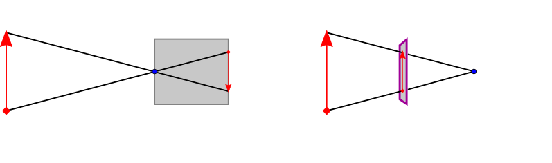
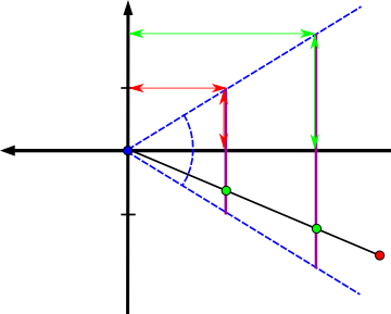
$\tilde{\mathbf{P}}= \left( f \frac{p_x}{p_z}, f \frac{p_y}{p_z}, f \right)^\top$
$\frac{\tilde{p}_x}{f} = \frac{p_x}{p_z}$ and $\frac{\tilde{p}_y}{f} = \frac{p_y}{p_z}$
$\tilde{\mathbf{P}}= \begin{pmatrix} \tilde{p}_x \\ \tilde{p}_y \\ \tilde{p}_z \end{pmatrix}= \begin{pmatrix} f \frac{p_x}{p_z}\\ f \frac{p_y}{p_z}\\ f \end{pmatrix} \in \mathbb{R}^3 \longmapsto \underline{\tilde{\mathbf{P}}}= \begin{pmatrix}f \, p_x \\f \, p_y \\ f \, p_z\\ p_z\end{pmatrix} \in \mathbb{H}^3$
$\begin{align}\underline{\tilde{\mathbf{P}}} & = \begin{pmatrix}f \, p_x \\f \, p_y \\ f \, p_z\\ p_z\end{pmatrix} = \underbrace{\begin{bmatrix} f & 0 & 0 & 0 \\ 0 & f & 0 & 0 \\ 0 & 0 & f & 0 \\ 0 & 0 & 1 & 0 \end{bmatrix}}_{\mathtt{A}} \begin{pmatrix}p_x \\p_y \\ p_z\\ 1\end{pmatrix}\\ \underline{\tilde{\mathbf{P}}} &=\mathtt{A}\, \underline{\mathbf{P}} \end{align}$
$\begin{align}\underline{\tilde{\mathbf{P}}} & = \begin{pmatrix}f \, p_x \\f \, p_y \\ f \, p_z\\ -p_z\end{pmatrix} = \underbrace{\begin{bmatrix} f & 0 & 0 & 0 \\ 0 & f & 0 & 0 \\ 0 & 0 & f & 0 \\ 0 & 0 & -1 & 0 \end{bmatrix}}_{\mathtt{A}} \begin{pmatrix}p_x \\p_y \\ p_z\\ 1\end{pmatrix}\\ \underline{\tilde{\mathbf{P}}} &=\mathtt{A}\, \underline{\mathbf{P}} \end{align}$
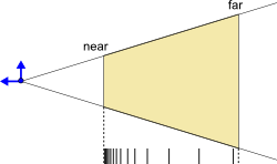
$p_z=-z_n \quad \mapsto \quad \tilde{p}_z=-1$
and for points on the far-plane:
$p_z=-z_f \quad \mapsto \quad \tilde{p}_z=1$
$\underline{\tilde{\mathbf{P}}} = \begin{pmatrix}f \, p_x \\f \, p_y \\ \alpha \, p_z + \beta \\ -p_z\end{pmatrix} = \begin{bmatrix} f & 0 & 0 & 0 \\ 0 & f & 0 & 0 \\ 0 & 0 & \alpha & \beta \\ 0 & 0 & -1 & 0 \end{bmatrix} \begin{pmatrix}p_x \\p_y \\ p_z\\ 1\end{pmatrix} \in \mathbb{H}^3$
$\tilde{\mathbf{P}}=(\tilde{p}_x,\tilde{p}_y,\tilde{p}_z)^\top = \left( f \frac{p_x}{-p_z}, f \frac{p_y}{-p_z}, -\alpha \, + \frac{\beta}{-p_z} \right)^\top \in \mathbb{R}^3$
$\begin{align} \alpha &= \frac{z_f+z_n}{z_n-z_f}\\ \beta & = \frac{2 z_f \, z_n}{z_n-z_f}\end{align}$
$\begin{align} \underline{\tilde{\mathbf{P}}} & = \underbrace{\begin{bmatrix} f & 0 & 0 & 0 \\ 0 & f & 0 & 0 \\ 0 & 0 & \frac{z_f+z_n}{z_n-z_f} & \frac{2 z_f \, z_n}{z_n-z_f} \\ 0 & 0 & -1 & 0 \end{bmatrix}}_{\mathtt{A}} \begin{pmatrix}p_x \\p_y \\ p_z\\ 1\end{pmatrix}\\ \underline{\tilde{\mathbf{P}}} &=\mathtt{A}\, \underline{\mathbf{P}} \end{align}$
$\frac{f}{1} = \frac{\cos( 0.5 \, \Theta)}{\sin( 0.5 \, \Theta)} \Leftrightarrow f = \mathrm{cotan}( 0.5 \, \Theta)$
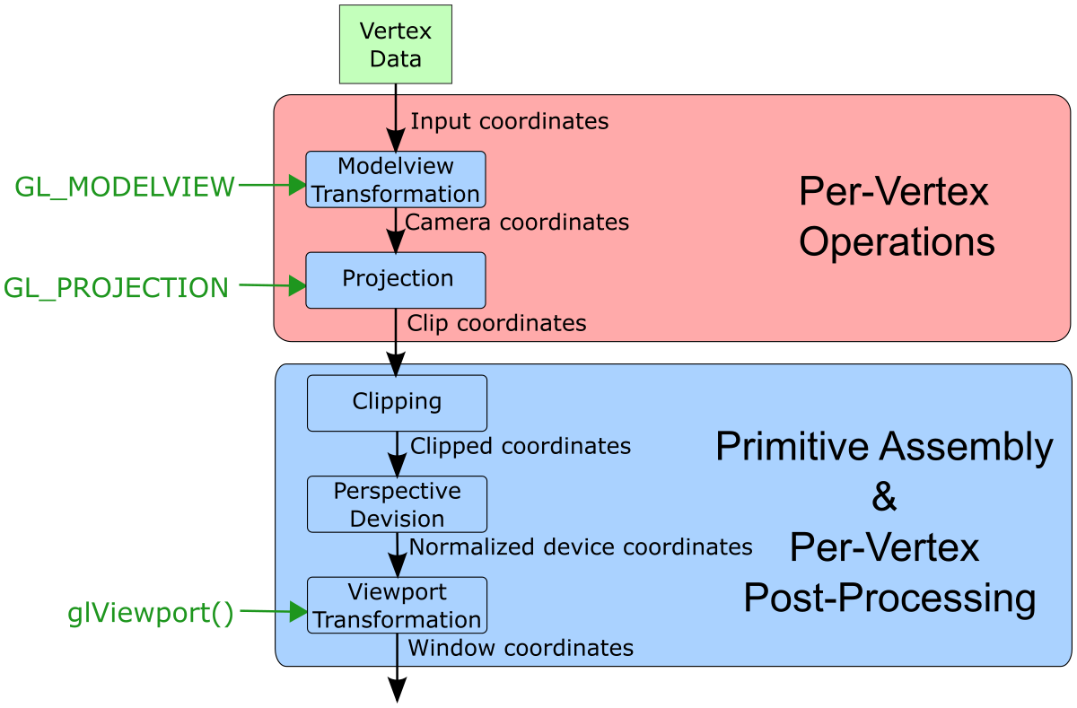
GL_PROJECTION matrix is used.glMatrixMode(GL_PROJECTION);
glLoadIdentity, glLoadMatrix, glMultMatrix, glRotate,
               glScale, glTranslate, glPushMatrix, glPopMatrix, gluPerspective
are then executed on the GL_PROJECTION matrix.
GL_PROJECTION matrix influences the transformation of objects only if they are drawn (OpenGL as a state machine)Creating a perspective projection matrix in OpenGL:
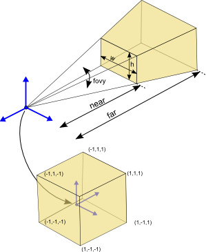
glMatrixMode(GL_PROJECTION);
glLoadIdentity();
gluPerspective(fovy, aspect, near, far);
$ \mathtt{A} = \begin{bmatrix} \frac{f}{\mathrm{aspect}} & 0 & 0 & 0 \\ 0 & f & 0 & 0 \\ 0 & 0 & \frac{\mathrm{far}+\mathrm{near}}{\mathrm{near}-\mathrm{far}} & \frac{2 \ast \mathrm{far} \ast \mathrm{near}}{\mathrm{near}-\mathrm{far}} \\ 0 & 0 & -1 & 0 \end{bmatrix}$
with $f = \mathrm{cotan}( 0.5 \ast \mathrm{fovy})$
and $\mathrm{aspect}= \mathrm{w} / \mathrm{h}$
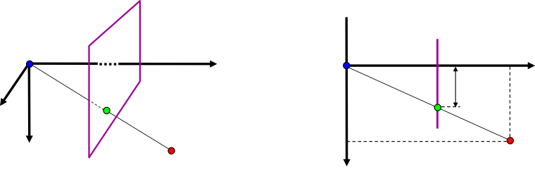
$\tilde{p}_y = f \frac{p_y}{-p_z}$
class Renderer {
public:
float t; //time
const float d0; // initial distance
public:
Renderer() : t(1.0), d0(3.0), width(0), height(0) {}
public:
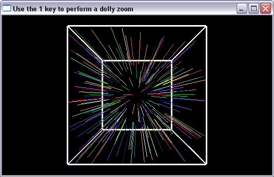
void display() {
glClearColor(0.0f, 0.0f, 0.0f, 0.0f);
glClear(GL_COLOR_BUFFER_BIT | GL_DEPTH_BUFFER_BIT);
glMatrixMode(GL_PROJECTION);
glLoadIdentity();
gluPerspective (dollyZoomFovy(),
(float)width/(float)height,
0.1, 50.0);
glMatrixMode(GL_MODELVIEW);
glLoadIdentity();
// translate camera by 3 units
glTranslatef(0.0f, 0.0f, -t*d0);
// draw a cube in the local coordinate system
drawCube();
// draw random lines
drawRandomLines();
}
void init() {
glEnable(GL_DEPTH_TEST);
// create random values between -1.0 and 1.0
for(unsigned r=0; r < 1000; r++) {
int r = rand();
randVals.push_back(2.0*float(r)/float(RAND_MAX)-1.0f);
}
}
void resize(int w, int h) {
// ignore this for now
glViewport(0, 0, w, h);
width = w;
height = h;
}
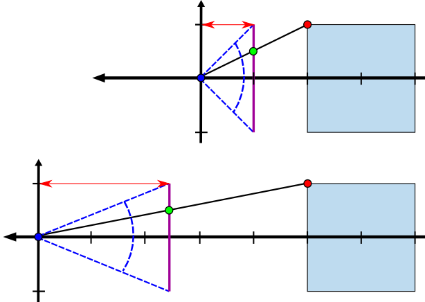
float dollyZoomFovy() {
float fovyInit = 60.0f; // initial field of view
float theta = fovyInit / 180.0f * M_PI; // degree to rad
float f = 1.0f / tan(theta/2.0f);
float fNew = f * (d0*t-1) / (d0-1);
float thetaNew = atan(1.0f / fNew) * 2.0f;
float val = 180.0 * thetaNew / M_PI; //rad to degree
return val;
}
private:
int width;
int height;
std::vector<float> randVals;
private:
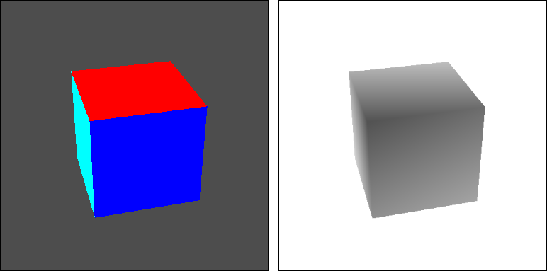
void drawCube() {
glColor3f(1.0f, 1.0f, 1.0f);
glLineWidth(3.0f);
glBegin(GL_LINE_LOOP);
glVertex3f(-1.0f, 1.0f, 1.0f);
glVertex3f( 1.0f, 1.0f, 1.0f);
glVertex3f( 1.0f,-1.0f, 1.0f);
glVertex3f(-1.0f,-1.0f, 1.0f);
glEnd();
glBegin(GL_LINE_LOOP);
glVertex3f(-1.0f, 1.0f,-1.0f);
glVertex3f( 1.0f, 1.0f,-1.0f);
glVertex3f( 1.0f,-1.0f,-1.0f);
glVertex3f(-1.0f,-1.0f,-1.0f);
glEnd();
glBegin(GL_LINE_LOOP);
glVertex3f( 1.0f, 1.0f,-1.0f);
glVertex3f( 1.0f, 1.0f, 1.0f);
glVertex3f( 1.0f,-1.0f, 1.0f);
glVertex3f( 1.0f,-1.0f,-1.0f);
glEnd();
glBegin(GL_LINE_LOOP);
glVertex3f(-1.0f, 1.0f,-1.0f);
glVertex3f(-1.0f, 1.0f, 1.0f);
glVertex3f(-1.0f,-1.0f, 1.0f);
glVertex3f(-1.0f,-1.0f,-1.0f);
glEnd();
glLineWidth(1.0);
}
void drawRandomLines() {
if(randVals.size() % 5) return;
unsigned i = 0;
while(i < randVals.size()) {
glColor3f(fabs(randVals[i++]),
fabs(randVals[i++]),
fabs(randVals[i++]));
float x = randVals[i++];
float y = randVals[i++];
glBegin(GL_LINES);
glVertex3f(x, y, -1.0f);
glVertex3f(x, y, 1.0f);
glEnd();
}
}
};
$\underline{\tilde{\mathbf{P}}} = \mathtt{A} \, \mathtt{T}_{\mathrm{\small cam}}^{-1} \, \mathtt{T}_{\mathrm{\small obj}} \, \underline{\mathbf{P}}$
Mapping equation for homogeneous points:
$\underline{\tilde{\mathbf{P}}} = \mathtt{A} \, \mathtt{T}_{\mathrm{\small cam}}^{-1} \, \mathtt{T}_{\mathrm{\small obj}} \, \underline{\mathbf{P}}$
where the $4 \times 4$ matrix
$ \mathtt{T}_{\mathrm{\small obj}} = \begin{bmatrix}\tilde{\mathbf{b}}_x & \tilde{\mathbf{b}}_y & \tilde{\mathbf{b}}_z & \mathbf{C}_b\\0 & 0 & 0 & 1\end{bmatrix}$
$\begin{align} \mathtt{T}_{\mathrm{\small cam}} & = \begin{bmatrix}\tilde{\mathbf{a}}_x & \tilde{\mathbf{a}}_y & \tilde{\mathbf{a}}_z & \mathbf{C}_a\\0 & 0 & 0 & 1\end{bmatrix} \\ & = \begin{bmatrix} \mathtt{R}_a & \mathbf{C}_a\\ \mathbf{0}^\top & 1\end{bmatrix} \end{align}$
$\mathtt{T}_{\mathrm{\small cam}}^{-1} = \begin{bmatrix} \mathtt{R}_a & \mathbf{C}_a\\ \mathbf{0}^\top & 1\end{bmatrix}^{-1} = \begin{bmatrix} \mathtt{R}_a^{\top} & -\mathtt{R}_a^{\top} \mathbf{C}_a\\ \mathbf{0}^\top & 1\end{bmatrix} $
Mapping equation for homogeneous points:
$\underline{\tilde{\mathbf{P}}} = \mathtt{A} \, \underbrace{\mathtt{T}_{\mathrm{\small cam}}^{-1} \, \mathtt{T}_{\mathrm{\small obj}}}_{\mathtt{T}_{\mathrm{\small modelview}}} \, \underline{\mathbf{P}}$
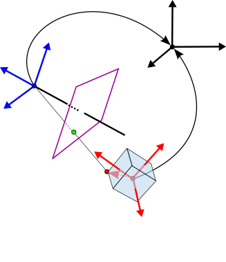
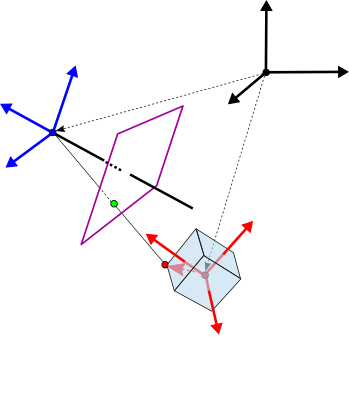
GL_MODELVIEW matrixGL_MODELVIEW matrix directly describes the transformation from the respective local coordinate system to the camera coordinate systemGL_PROJECTION matrix $\mathtt{A}$ describes the mapping from the camera coordinate system into the image planegluLookAt(eyex, eyey, eyez, refx, refy, refz, upx, upy, upz);
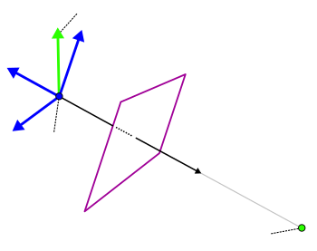
$\begin{align} \mathbf{d} & = \mathbf{C}_{\mathrm{\small eye}} - \mathbf{P}_{\mathrm{\small ref}}\\ \tilde{\mathbf{a}}_z &= \frac{\mathbf{d}}{|\mathbf{d}|}, \mathbf{v}' = \frac{\mathbf{v}_{\mathrm{\small up}}}{|\mathbf{v}_{\mathrm{\small up}}|} \\ \tilde{\mathbf{a}}_x &= \mathbf{v}'\times \tilde{\mathbf{a}}_z \\ \tilde{\mathbf{a}}_y &= \tilde{\mathbf{a}}_z \times \tilde{\mathbf{a}}_x\\ \mathtt{R}_{a} & = \begin{bmatrix}\tilde{\mathbf{a}}_x & \tilde{\mathbf{a}}_y & \tilde{\mathbf{a}}_z \end{bmatrix} \\ \end{align}$
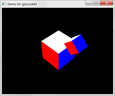
class Renderer {
  ...
  void resize(int w, int h) {
    glViewport(0, 0, w, h);
    glMatrixMode(GL_PROJECTION);
    glLoadIdentity();
    gluPerspective (30.0, (float)w/(float)h, 2.0, 20.0);
  }
  void display() {
    glClearColor(0.0f, 0.0f, 0.0f, 0.0f);
    glClear(GL_COLOR_BUFFER_BIT | GL_DEPTH_BUFFER_BIT);
    glMatrixMode(GL_MODELVIEW);
    glLoadIdentity();

    // camera orbits in the y=10 plane
    // and looks at origin
    double rad = M_PI / 180.0f * t;
    gluLookAt(10.0*cos(rad), 10.0 , 10.0*sin(rad), // eye
              0.0, 0.0, 0.0, // look at
              0.0, 1.0, 0.0); // up

    //draw cube at origin
    drawCube();

    glRotatef(45.0f, 0.0f, 0.0f, 1.0f);
    glTranslatef(2.5f, 0.0f, 0.0f );
    glScalef(0.5f, 0.5f, 0.5f);

    //draw transformed cube
    drawCube();
  }
  ...
}
glMatrixMode(GL_PROJECTION);
glLoadIdentity();
gluPerspective (...);

glMatrixMode(GL_MODELVIEW);
glLoadIdentity();
gluLookAt(...);


glRotatef(...);
glTranslatef(...);
glScalef(...);
$\mathtt{T}_{\mathrm{\small projection}}= \mathtt{I}$
$\mathtt{T}_{\mathrm{\small projection}}= \mathtt{I} \, \mathtt{A}$
$\mathtt{T}_{\mathrm{\small modelview}}= \mathtt{I}$
$\mathtt{T}_{\mathrm{\small modelview}}= \mathtt{I}\,\mathtt{T}_{\mathrm{\small cam}}^{-1}$
$\mathtt{T}_{\mathrm{\small modelview}}= \mathtt{I}\,\mathtt{T}_{\mathrm{\small cam}}^{-1} \,\mathtt{T}_r$
$\mathtt{T}_{\mathrm{\small modelview}}= \mathtt{I}\,\mathtt{T}_{\mathrm{\small cam}}^{-1} \,\mathtt{T}_r\,\mathtt{T}_t$
$\mathtt{T}_{\mathrm{\small modelview}}= \mathtt{I}\,\mathtt{T}_{\mathrm{\small cam}}^{-1} \,\mathtt{T}_r\,\mathtt{T}_t\,\mathtt{T}_s $
$\begin{align} \underline{\tilde{\mathbf{P}}} &= \mathtt{T}_{\mathrm{\small projection}} \mathtt{T}_{\mathrm{\small modelview}} \, \underline{\mathbf{P}}\\ &= \mathtt{A} \, \mathtt{T}_{\mathrm{\small cam}}^{-1} \,\mathtt{T}_r\,\mathtt{T}_t\,\mathtt{T}_s \,\underline{\mathbf{P}} \end{align}$
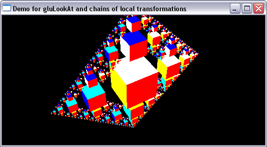
class Renderer {
public:
  float t;

public:
  Renderer() : t(0.0) {}

public:
  void display() {
    glClearColor(0.0f, 0.0f, 0.0f, 0.0f);
    glClear(GL_COLOR_BUFFER_BIT | GL_DEPTH_BUFFER_BIT);

    glMatrixMode(GL_MODELVIEW);
    glLoadIdentity();

    // camera orbits in the y=10 plane
    // and looks at origin
    double rad = M_PI / 180.0f * t;
    gluLookAt(10.0*cos(rad), 10.0 , 10.0*sin(rad), // eye
              0.0, 0.0, 0.0, // look at
              0.0, 1.0, 0.0); // up

    //draw model at origin
    drawCubeHierarchy(0, 4);
  }

  void init() {
    glEnable(GL_DEPTH_TEST);
  }

  void resize(int w, int h) {
    glViewport(0, 0, w, h);
    glMatrixMode(GL_PROJECTION);
    glLoadIdentity();
    gluPerspective (30.0, (float)w/(float)h, 0.1, 50.0);
  }

private:
  void drawCube() {
    ...
  }

  void drawCubeHierarchy(int depth, int neighbors) {
    drawCube(); // draw parent
    depth +=1;
    if (depth < 6){
      for (int n = 0; n < neighbors; n++){
        glPushMatrix();
        glRotatef(n*90.0f-90.0f, 0.0f, 0.0f, 1.0f);
        glTranslatef(2.5f, 0.0f, 0.0f );
        glScalef(0.5f, 0.5f, 0.5f);
        drawCubeHierarchy(depth, 3); // draw children
        glPopMatrix();
      }
    }
  }
};
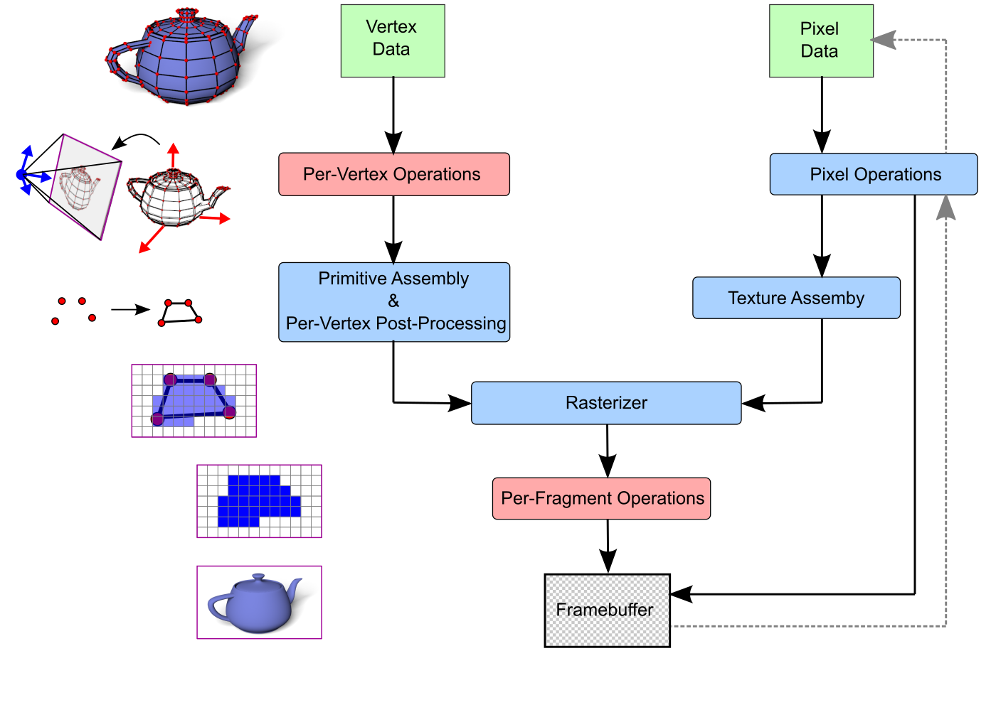
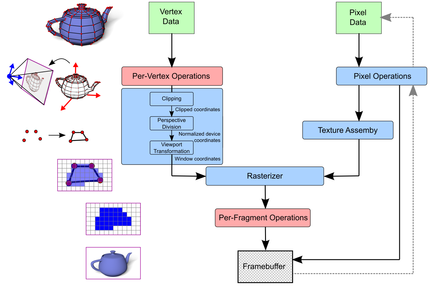
When using the fixed-function pipeline the following transformations are applied on the vertex data
$\underline{\mathbf{P}} = \begin{pmatrix}p_x\\p_y\\p_z\\p_w\end{pmatrix} \in \mathbb{H}^3 \quad \longmapsto \quad \mathbf{P}= \begin{pmatrix}\frac{p_x}{p_w}\\\frac{p_y}{p_w}\\\frac{p_z}{p_w} \end{pmatrix} \in \mathbb{R}^3 $
$-p_w < p_x < p_w \quad \longmapsto \quad -1 < \frac{p_x}{p_w} < 1$
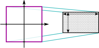
glViewport(int ix, int iy, int width, int height)
ix and iy define the lower-left corner of the viewport and width and height the screen size (the unit is pixels)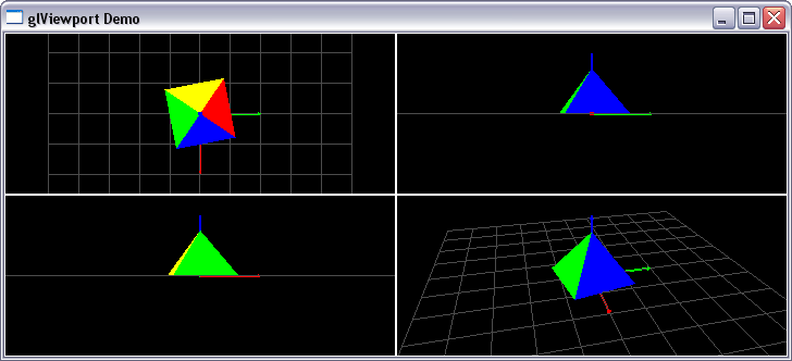
class Renderer {

public:
  float t;

public:
  Renderer() : t(0.0), width(0), height(0) {}

public:
  void display() {
    glClearColor(0.0f, 0.0f, 0.0f, 0.0f);
    glClear(GL_COLOR_BUFFER_BIT | GL_DEPTH_BUFFER_BIT);

    // top right viewport (look from front)
    glViewport(width/2, height/2, width/2, height/2);
    glMatrixMode(GL_MODELVIEW);
    glLoadIdentity();
    drawFrame();
    // set camera (look from positive x-direction)
    gluLookAt(10.0, 0.0, 0.0,
               0.0, 0.0, 0.0,
               0.0, 0.0, 1.0);
    // draw scene
    drawSceneGrid();
    drawRotatingPyramid();

    // bottom left viewport (look from left)
    glViewport(0, 0, width/2, height/2);
    glMatrixMode(GL_MODELVIEW);
    glLoadIdentity();
    drawFrame();
     // set camera (look from negative y-direction)
    gluLookAt(0.0, -10.0, 0.0,
              0.0,   0.0, 0.0,
              0.0,   0.0, 1.0);
    // draw scene
    drawSceneGrid();
    drawRotatingPyramid();

    // top left viewport (look from top)
    glViewport(0, height/2, width/2, height/2);
    glMatrixMode(GL_MODELVIEW);
    glLoadIdentity();
    drawFrame();
    // set camera (look from positive z-direction)
     gluLookAt(0.0, 0.0, 10.0,
               0.0, 0.0,  0.0,
              -1.0, 0.0,  0.0);
    // draw scene
    drawSceneGrid();
    drawRotatingPyramid();

    // bottom right viewport (perspective)
    glViewport(width/2, 0, width/2, height/2);
    glMatrixMode(GL_MODELVIEW);
    glLoadIdentity();
    drawFrame();
    // set camera
    gluLookAt(8.0, -2.0, 5.0,
              0.0,  0.0, 0.0,
              0.0,  0.0, 1.0);
    // draw scene
    drawSceneGrid();
    drawRotatingPyramid();
  }

  void init() {
    glEnable(GL_DEPTH_TEST);
    //glEnable(GL_CULL_FACE);
  }

  void resize(int w, int h) {
    width = w;
    height = h;
    glMatrixMode(GL_PROJECTION);
    glLoadIdentity();
    gluPerspective (30.0,
                    (float)width/(float)height,
                    0.1, 50.0);
  }

private:
  int width;
  int height;

private:
  void drawFrame() {
      glLineWidth(2.0);
      glMatrixMode(GL_PROJECTION);
      glPushMatrix();
      glLoadIdentity();
      glColor3f(1.0f, 1.0f, 1.0f);
      glBegin(GL_LINE_LOOP);
      glVertex3f(-1.0f, 1.0f, 0.0f);
      glVertex3f( 1.0f, 1.0f, 0.0f);
      glVertex3f( 1.0f,-1.0f, 0.0f);
      glVertex3f(-1.0f,-1.0f, 0.0f);
      glEnd();
      glPopMatrix();
      glMatrixMode(GL_MODELVIEW);
      glLineWidth(1.0);
  }

  void drawSceneGrid() {
      glColor3f(0.3f, 0.3f, 0.3f);
      glBegin(GL_LINES);
      for(unsigned i=0; i<=10; i++) {
        glVertex3f(-5.0f+i, -5.0f,   0.0f);
        glVertex3f(-5.0f+i,  5.0f,   0.0f);
        glVertex3f(-5.0f,   -5.0f+i, 0.0f);
        glVertex3f( 5.0f,   -5.0f+i, 0.0f);
      }
      glEnd();

    glColor3f(0.0f, 0.0f, 1.0f);
    drawCoordinateAxisZ();
    glColor3f(0.0f, 1.0f, 0.0f);
    drawCoordinateAxisY();
    glColor3f(1.0f, 0.0f, 0.0f);
    drawCoordinateAxisX();
  }

  void drawCoordinateAxisZ() {
    glLineWidth(2.0);
    glBegin(GL_LINES);
    glVertex3f(0.0f, 0.0f, 0.0f); // z-axis
    glVertex3f(0.0f, 0.0f, 2.0f);
    glEnd();
    glLineWidth(1.0);

    // z-axis tip
    glBegin(GL_TRIANGLES);
    glVertex3f( 0.0f, 0.0f, 2.0f);
    glVertex3f(-0.05f, 0.05f, 1.9f);
    glVertex3f( 0.05f, 0.05f, 1.9f);
    glVertex3f( 0.0f,  0.0f, 2.0f);
    glVertex3f( 0.05f, -0.05f, 1.9f);
    glVertex3f(-0.05f, -0.05f, 1.9f);
    glVertex3f( 0.0f,  0.0f, 2.0f);
    glVertex3f( 0.05f,  0.05f, 1.9f);
    glVertex3f( 0.05f, -0.05f, 1.9f);
    glVertex3f( 0.0f,  0.0f, 2.0f);
    glVertex3f(-0.05f, -0.05f, 1.9f);
    glVertex3f(-0.05f,  0.05f, 1.9f);
    glEnd();
    glBegin(GL_POLYGON);
    glVertex3f( 0.05f, -0.05f, 1.9f);
    glVertex3f( 0.05f,  0.05f, 1.9f);
    glVertex3f(-0.05f,  0.05f, 1.9f);
    glVertex3f(-0.05f, -0.05f, 1.9f);
    glEnd();
  }

  void drawCoordinateAxisX() {
      glPushMatrix();
      glRotatef(90.0f, 0.0f, 1.0f, 0.0f);
      drawCoordinateAxisZ();
      glPopMatrix();
  }

  void drawCoordinateAxisY() {
      glPushMatrix();
      glRotatef(-90.0f, 1.0f, 0.0f, 0.0f);
      drawCoordinateAxisZ();
      glPopMatrix();
  }

  void drawRotatingPyramid() {
    glRotatef(t, 0.0f, 0.0f, 1.0f);
    drawPyramid();
  }

  void drawPyramid() {
    glColor3f(1.0,0.0,0.0);
    glBegin(GL_TRIANGLES);
    glVertex3f( 0.0f, 0.0f, 1.5f);
    glVertex3f(-1.0f, 1.0f, 0.0f);
    glVertex3f( 1.0f, 1.0f, 0.0f);
    glEnd();
    glColor3f(0.0,1.0,0.0);
    glBegin(GL_TRIANGLES);
    glVertex3f( 0.0f,  0.0f, 1.5f);
    glVertex3f( 1.0f, -1.0f, 0.0f);
    glVertex3f(-1.0f, -1.0f, 0.0f);
    glEnd();
    glColor3f(0.0,0.0,1.0);
    glBegin(GL_TRIANGLES);
    glVertex3f( 0.0f,  0.0f, 1.5f);
    glVertex3f( 1.0f,  1.0f, 0.0f);
    glVertex3f( 1.0f, -1.0f, 0.0f);
    glEnd();
    glColor3f(1.0,1.0,0.0);
    glBegin(GL_TRIANGLES);
    glVertex3f( 0.0f,  0.0f, 1.5f);
    glVertex3f(-1.0f, -1.0f, 0.0f);
    glVertex3f(-1.0f,  1.0f, 0.0f);
    glEnd();
    glColor3f(0.0,1.0,1.0);
    glBegin(GL_POLYGON);
    glVertex3f( 1.0f, -1.0f, 0.0f);
    glVertex3f( 1.0f,  1.0f, 0.0f);
    glVertex3f(-1.0f,  1.0f, 0.0f);
    glVertex3f(-1.0f, -1.0f, 0.0f);
    glEnd();
  }
};
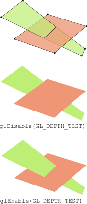
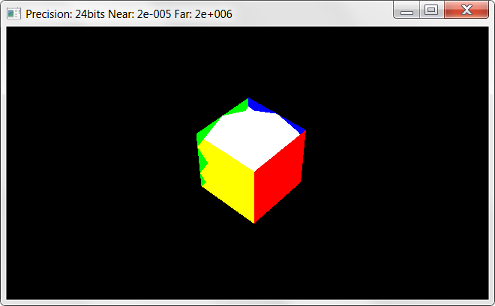
glEnable(GL_DEPTH_TEST)
and glClear(GL_DEPTH_BUFFER_BIT) were used without discussing their functionalityglEnable(GL_DEPTH_TEST) is used to activated the depth test in OpenGL
glClear(GL_DEPTH_BUFFER_BIT)FOR each primitiv
FOR each pixel of primitive at position (x,y) with colour c and depth d
IF d < depthbuffer(x,y)
framebuffer(x,y) = c
depthbuffer(x,y) = d
END IF
END FOR
END FOR
class Renderer {

public:
  float t;
  int width, height;
  double nearPlane, farPlane;
  int depthBits;

public:
  Renderer() : t(0.0), nearPlane(2.0), farPlane(20.0) {}

public:

  void resize(int w, int h) {
    glViewport(0, 0, w, h);
    width = w;
    height = h;
  }

  void display() {
    glClearColor(0.0f, 0.0f, 0.0f, 0.0f);
    glClear(GL_COLOR_BUFFER_BIT | GL_DEPTH_BUFFER_BIT);

    glMatrixMode(GL_PROJECTION);
    glLoadIdentity();
    gluPerspective (30.0, (float)width/(float)height, nearPlane, farPlane);
    glMatrixMode(GL_MODELVIEW);
    glLoadIdentity();

    // camera orbits in the y=10 plane
    // and looks at origin
    double rad = M_PI / 180.0f * t;
    gluLookAt(10.0*cos(rad), 10.0 , 10.0*sin(rad), // eye
              0.0, 0.0, 0.0, // look at
              0.0, 1.0, 0.0); // up

    //draw cube at origin
    drawCube();
  }

  void init() {
    glEnable(GL_DEPTH_TEST);
    glGetIntegerv (GL_DEPTH_BITS, &depthBits);
  }
private:
  void drawCube() {
    ...
  }
};
Please notify me by e-mail if you have questions, suggestions for improvement, or found typos: Contact